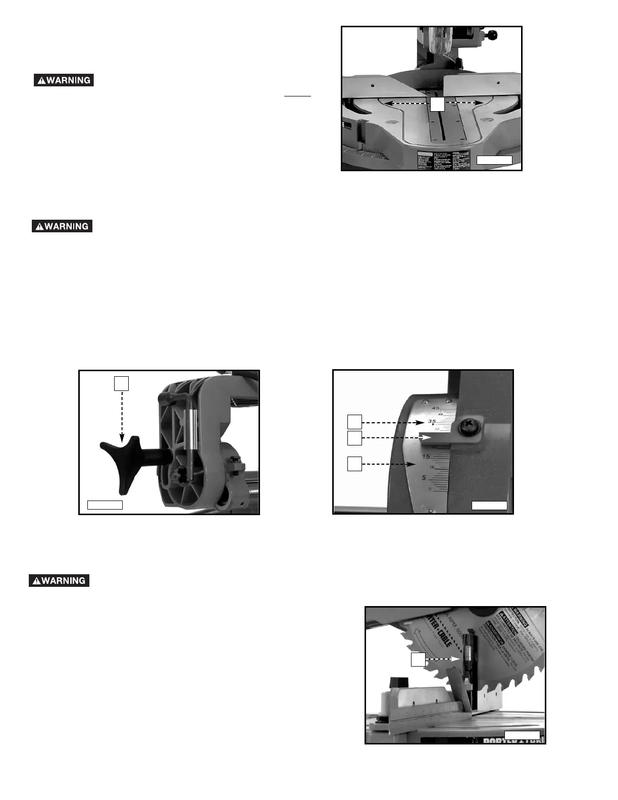
1. Loosen the bevel lock handle and check to see that the
cuttinghead is all the way to the right. Tighten the lock
handle.
2. Place one end of a square (A) Fig. 20 on the table and
the other end against the blade. The blade should be
90° to the table.
ADJUSTING 0° AND 45° BEVEL POSITIVE STOPS
DISCONNECT THE MACHINE FROM THE POWER SOURCE.
12
TILTING CUTTINGHEAD FOR BEVEL CUTTING
DISCONNECT THE MACHINE FROM THE POWER SOURCE.
IMPORTANT: Move the sliding fence to provide clearance for the blade and guard. The degree of tilt determines how far to
move the sliding fence. Refer to the section “ADJUSTING SLIDING FENCE.”
1. The cuttinghead can be tilted to cut any bevel angle from 90° to 45° left bevel. Loosen the bevel lock handle (A) Fig. 18,
tilt the cuttinghead to the desired angle, and tighten the lock handle (A).
2. Positive stops are provided to rapidly position the saw blade at 90° and 45°. Refer to the section of this manual titled
“ADJUSTING 90° AND 45° BEVEL POSITIVE STOPS.” The bevel angle of the cutting arm is determined by the position
of the pointer (A) Fig. 19 on scale (B).
3. In addition, a marked indicator (C) Fig. 19 is provided on the bevel scale (33.86°) for cutting crown moulding. Refer to the
“CUTTING CROWN MOULDING” section of this manual.
A
A
A
A
C
Fig. 18
Fig. 19
B
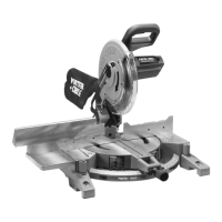
TABLE HAZARD ZONE
The area inside the red lines (A) Fig. 17 on the
table is designated as a HAZARD ZONE. Never
place your hands inside this area while the tool
is being operated. Always use a clamp to
secure short workpieces.
A
Fig. 17
Fig. 20
A