10
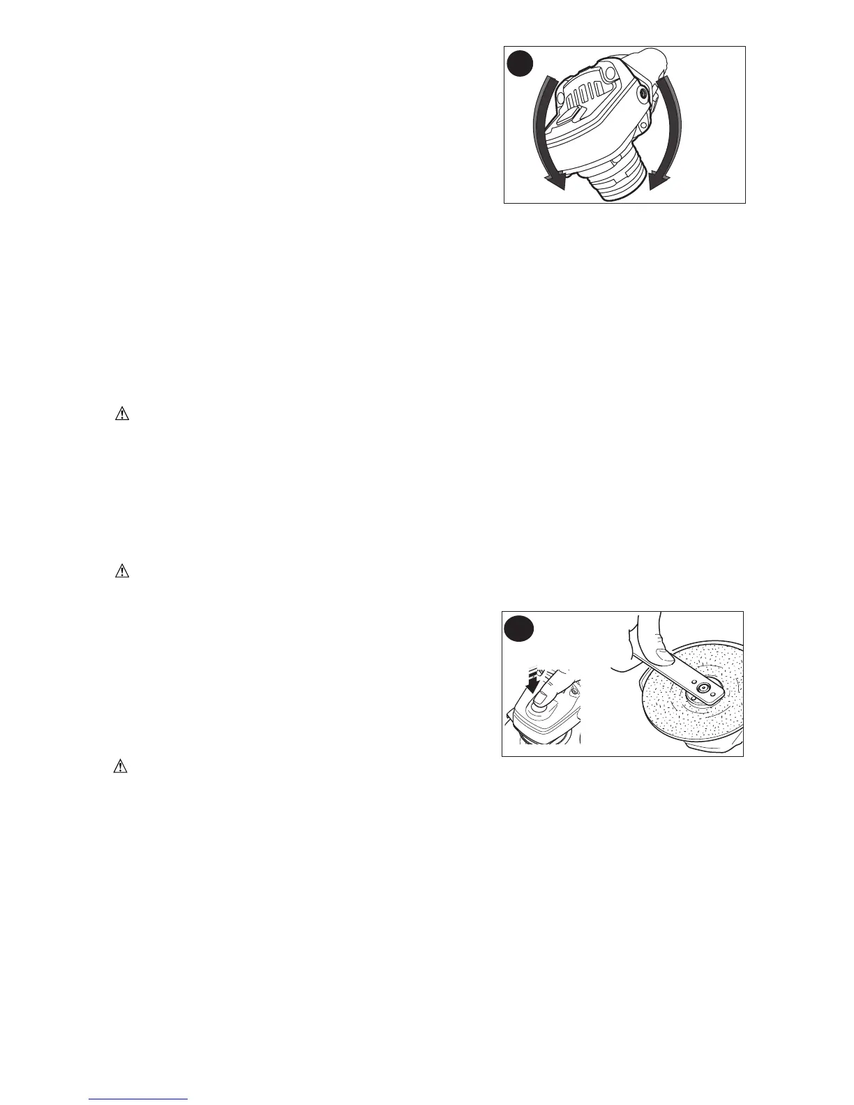
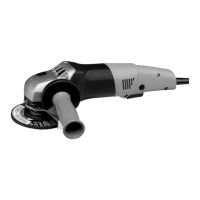
ROTATING THE GEAR CASE (FIG. E)
Turn off and unplug tool before making any
adjustments or removing or installing accessories.
Before reconnecting the tool, depress and release the
trigger switch to ensure that the tool is off.
1. Remove guard and flanges from tool.
2. Remove the four corner screws attaching the gear
case to motor housing.
3. Separating the gear case from motor housing not
more than 1/4 in., rotate the gear case head to
desired position.
NOTE: If the gear case and motor housing become separated by more than 1/4 in., the
tool must be serviced and re-assembled by a Porter Cable service center. Failure to
have the tool serviced may cause brush, motor and bearing failure.
4. Re-install screws to attach the gear case to the motor housing.
Tighten screws to 18 in./lbs. torque. Overtightening could cause screws to strip.
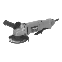
SPINDLE LOCK
The spindle lock button (6) is provided to prevent the spindle from rotating when installing
or removing wheels. Operate the spindle lock only when the tool is turned off and the
wheel has come to a complete stop.
WARNING: Do not engage the spindle lock while the tool is operating. Damage
to the tool will result and attached accessory may spin off possibly resulting in injury.
To engage the lock, depress the spindle lock button shown in figure E1 and rotate the
spindle until you are unable to rotate the spindle further.
MOUNTING AND USING DEPRESSED CENTER GRINDING WHEELS AND
SANDING FLAP DISCS
Mounting and Removing Hubbed Wheels
WARNING: To prevent accidental operation, turn off and unplug tool before
performing the following operations. Failure to do this could result in serious
personal injury.
Hubbed wheels install directly on the 5/8 in.-11
threaded spindle.
1. Thread the wheel on the spindle by hand.
2. Depress the spindle lock button and use a wrench
(figure E1) to tighten the hub of the wheel.
3. Reverse the above procedure to remove the
wheel.
CAUTION: Failure to properly seat the wheel
before turning the tool on may result in damage to the tool or the wheel.
E
90
o
90
o
E1