11
MOUNTING NON-HUBBED WHEELS
WARNING: To prevent accidental operation, turn off and unplug tool before
performing the following operations. Failure to do this could result in serious
personal injury.
Depressed center Type 27 grinding wheels must be used with included flanges. See
pages 9 and 10 of this manual for more information.
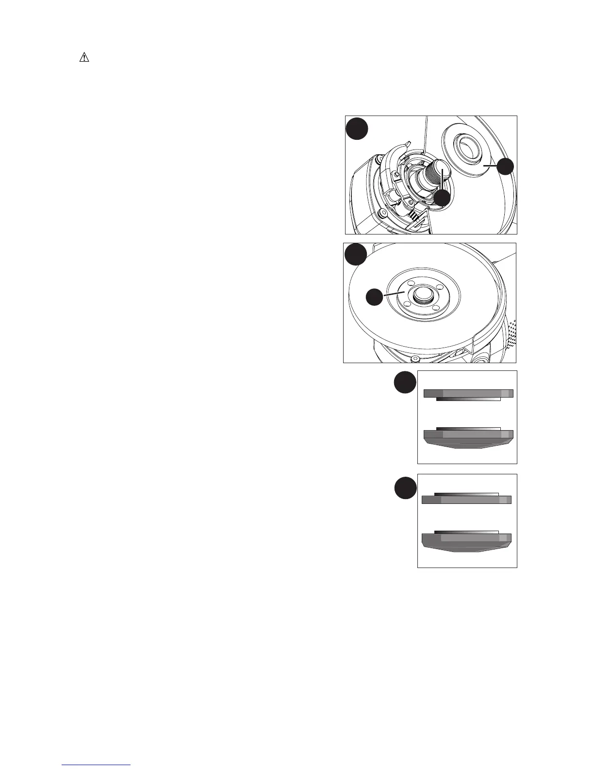
1. Figure F - Install the unthreaded backing flange
(11) on spindle (12) with the raised section (pilot)
against the wheel.
2. Place wheel against the backing flange, centering
the wheel on the raised section (pilot) of the
backing flange.
3. Figure G - While depressing the spindle lock
button, thread the threaded clamp nut (13) on
spindle.
• Figure H - If the wheel you are installing is more than 1/8 inch
(3mm) thick, place the threaded clamp nut on the spindle so
that the raised section (pilot) fits into the center of the wheel.
• Figure I - If the wheel you are installing is 1/8 inch (3mm)
thick or less, place the threaded clamp nut on the spindle so
that the raised section (pilot) is not against the wheel.
4. While depressing the spindle lock button (6), tighten the
threaded clamp nut with included wrench.
5. To remove the wheel, depress the spindle lock button and
loosen the threaded clamp nut with included wrench.
NOTE: If the wheel spins after the threaded clamp nut is tightened, check the orientation
of the threaded clamp nut. If a thin wheel is installed with the pilot on the clamp nut
against the wheel, it will spin because the height of the pilot prevents the clamp nut from
holding the wheel.
F
11
12
G
13
1/4 inch WHEELS
Backing Flange
Threaded Clamp Nut
1/8 inch WHEELS
Backing Flange
Threaded Clamp Nut
I
H