Hardware Configuration
RUBY-D716VG2AR User’s Manual 2-7
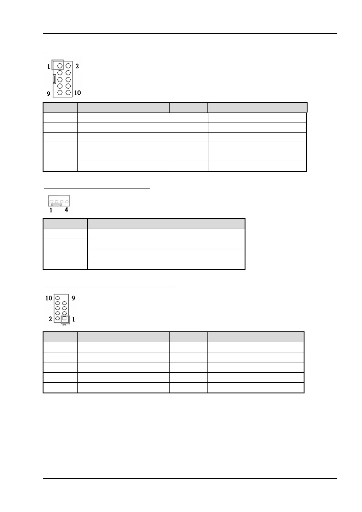
J12/J13/J14/J15/J17/J18/J19/J20: COM3~COM10 Serial Port Connector
PIN No. Signal Description PIN No. Signal Description
1 DCD (Data Carrier Detect)
2 DSR (Data Set Ready)
3 RXD (Receive Data) 4 RTS (Request to Send)
5 TXD (Transmit Data) 6 CTS (Clear to Send)
7 DTR (Data Terminal
Ready)
8 RI (Ring Indicator)
9 GND (Ground) 10 N/C
J16: CPU FAN Power Connector
PIN No. Signal Description
1 Ground
2 +12V
3 Fan on/off output
4 Fan Speed control
J25/J24/J23/J22: External USB Connector
PIN No. Signal Description PIN No. Signal Description
1 5V Dual 2 5V Dual
3 USB- 4 USB-
5 USB+ 6 USB+
7 Ground 8 Ground
9 10 N/C