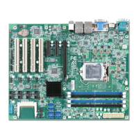
RUBY-D718VG2AR
Copyright © Portwell 2016 RUBY-D718VG2AR
User's Guide
4.2 Jumpers Settings
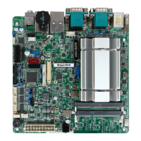
For users to customize RUBY-D718VG2AR‘s features. In the following sections, Short means covering a jumper cap over jumper pins; Open or N/C (Not
Connected) means removing a jumper cap from jumper pins. Users can refer to Figure 1 for the Jumper allocations.
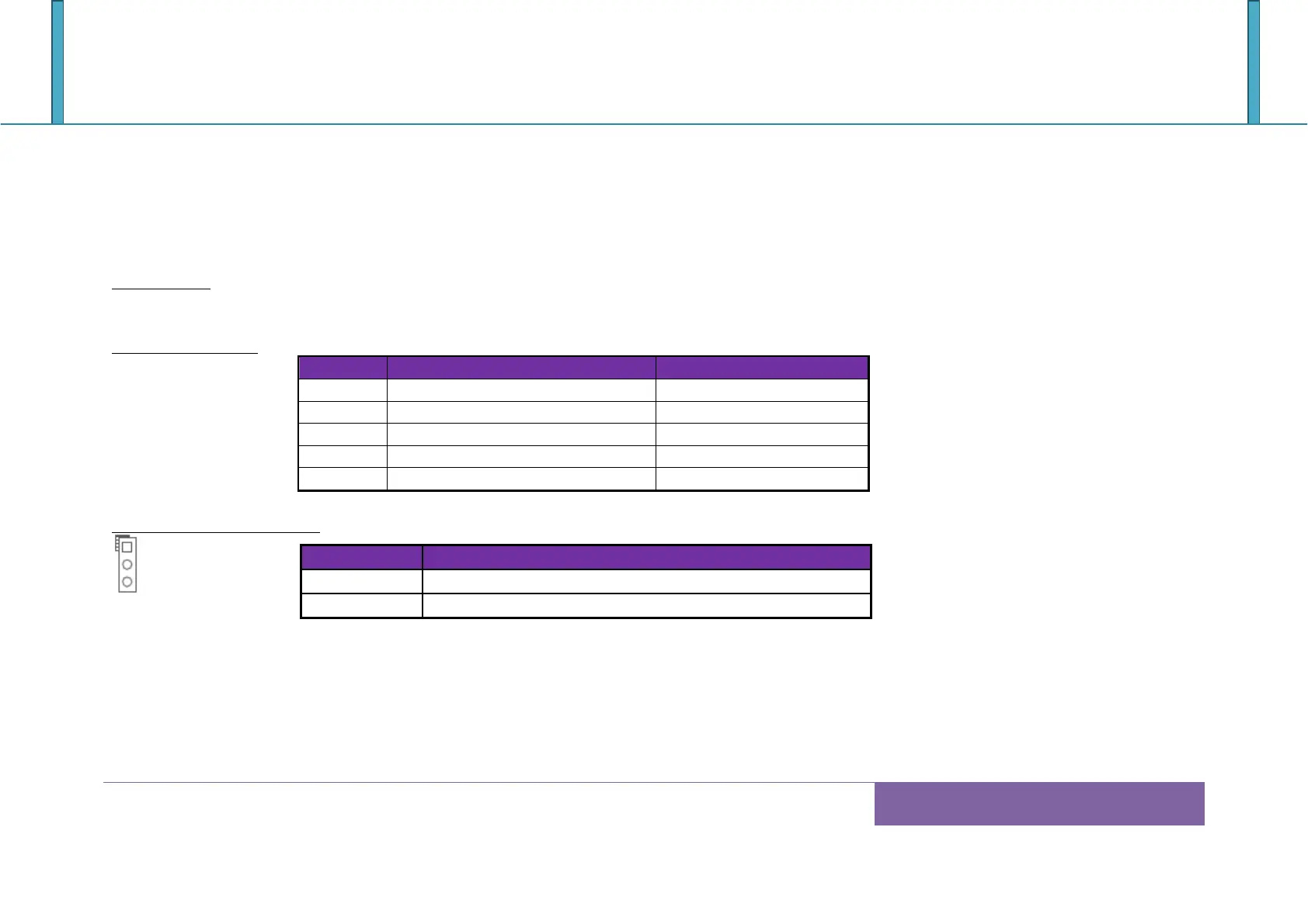
Jumper Table
The jumper settings are schematically depicted in this manual as follows:
Jump Function List:
AT /ATX Mode Select Jumper
RI Function Select Jumper
RI Function Select Jumper
JP1: AT/ATX Mode Selection