15
EVD-2 • 5401042 • REV L • 03/05
SENSITIVITY ADJUSTMENTS
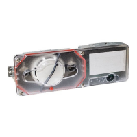
1. Adjust the EVD-M’s internal pickup sensitivity control, RV1, to 1/2 scale (12 o’clock
position). Refer to Figure 1 for adjustment location.
2. If remote pickups are installed, adjust the EVD-M’s remote pickup network
sensitivity control, RV2, to the minimum setting listed in Table 2. If no EVD-R’s are
installed, adjust RV2 to the minimum setting, fully counter-clockwise. Refer to
Figure 1 for adjustment location.
Table 2.
spukciPetomeRforebmuN 123456789 011121314151
krowteNetomeRmuminiM
gnitteSytivitisneS
000 4/14/14/14/14/12/12/12/12/12/14/34/3
3. Adjust accumulator rotary switch, S1, to desired setting. A setting of zero disables
the accumulator function. Refer to Figure 1 for adjustment location.
4. Perform simulated attack tests on all accessible surfaces that are protected by the
EVD-M and EVD-R’s. Strike the protected surfaces using a plastic mallet or the
plastic handle of a large screwdriver. An alarm condition (as indicated by the
status LED turning RED) must occur. Lightly scrape the blade of a screwdriver
next to the EVD-M and each EVD-R. After 15 seconds of continuous scraping,
an alarm condition (as indicated by the status LED turning RED) must occur. Be
sure the scraping generates a test point voltage greater than the
minimum constant noise level shown in Table 3. Adjust sensitivity settings
to the minimum needed to achieve desired level of response.
NOTE: Extreme care should be exercised so that the protected surfaces
are not marred or damaged while performing simulated attack tests.
A voltmeter can be connected to the analog test point and pin 2 of the field wiring
terminal block to aid the installer in adjusting the sensitivity controls. Refer to
Figure 1 for analog test point location.
Table 3. ANALOG TEST POINT LEVELS
noitpircseDlangiSleveLtnioPtseTgolanA
leveLesioNtneibmAmumixaMCDV02.0
muminiMtnatsnoC
mralArofesioN
)gnillirDtpecxe(
)noitarud.ces51.nim(
CDV52.0
muminiMelgniS
mralArofesioN
)nOrotalumuccA(
CDV07.0
muminiMelgniS
mralArofesioN
)ffOrotalumuccA(
CDV52.1
5. With the system operating in a non-alarm state, verify the operation of all tampers.
A tamper condition is indicated by the status LED turning AMBER. If the system
is in alarm when a tamper condition occurs, the status LED will remain
RED, identifying the alarm condition. The tamper alarm remote annuncia-
tor and the tamper alarm contact always identify a tamper condition.