7
EVD-2 • 5401042 • REV L • 03/05
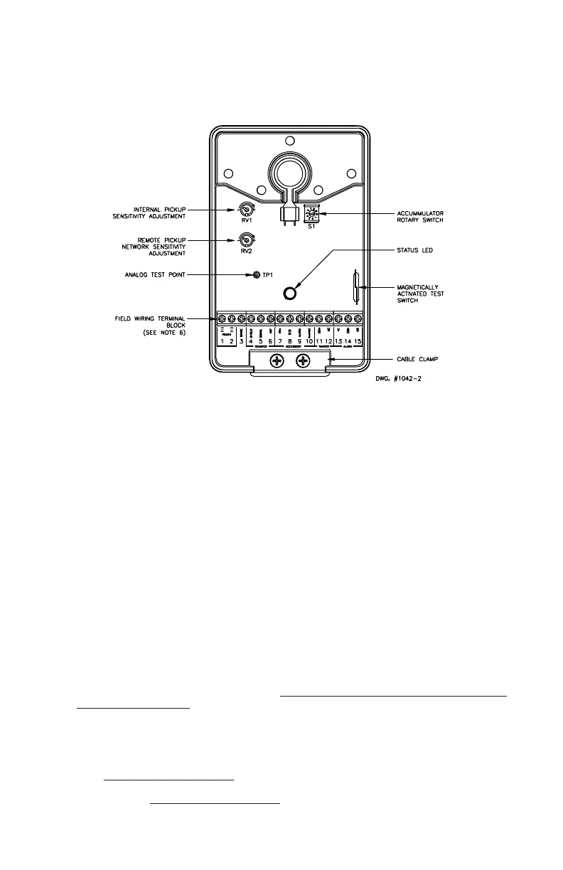
EVD-M TERMINAL CONNECTIONS
TERMINAL TERMINAL DESCRIPTION
NO. NAME
1 (+) Power Supply Connection, +12 VDC, nominal (See note 1)
2 (-) Power Supply Connection, 0 VDC (See note 1)
3 SPARE Spare Terminal Block Position
4 SHIELD Remote Pickup Cable Shield Connection or End of Line Resistor
(See note 2)
5 SIGNAL Remote Pickup Sensor Signal or End of Line Resistor (See note 2)
6 REF Remote Pickup Reference Signal or End of Line Resistor (See note 2)
7 RTN Accessory Return Connection (See note 3)
8 TEST Accessory Remote Test Input, Connect to RTN to Activate Test
(See note 3)
9 ALARM Accessory Remote Annunciator, Alarm (See notes 3, 4)
10 TAMPER Accessory Remote Annunciator, Tamper (See notes 3, 5)
11 COM Tamper Alarm Contact, Common
12 NC Tamper Alarm Contact, Normally Closed in NON-TAMPER STATE
13 NC Alarm Relay Contact, Normally Closed in NON-ALARM STATE
14 COM Alarm Relay Contact, Common
15 NO Alarm Relay Contact, Normally Open in NON-ALARM STATE
NOTES:
1. Observe polarity of power supply connections.
Application of voltages greater than 18 VDC may
result in damage to unit.
2. If EVD-R remote pickups are installed, remove the factory installed, 10K Ohm, 1% end of line
resistors from pins 4-5 and pins 5-6. See Figures 2a and 4 for details.
3. Connections to optional RTA, Remote Test Annunciator, or dry contacts from any UL listed central
station test unit. See Figure 5 for details.
4. Remote annunciator terminal provides power-limited +12 VDC when alarm contact is in its ALARM
state. Limit current draw to 10mA.
5. Remote annunciator terminal provides power-limited +12 VDC when tamper alarm contact is in its
TAMPER state. Limit current draw to 10mA.
6. Pins 1-15 are power limited.
Figure 1. EVD-M CONTROLLER DETAILS