12
EVD-2 • 5401042 • REV L • 03/05
RECOMMENDED CONTROL PANEL WIRING AND
REMOTE TEST AND ANNUNCIATOR CONNECTIONS
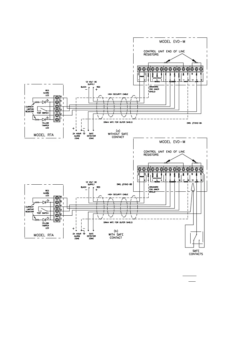
Figure 5a.
INSTALLATION
The EVD-2 System must be installed in accordance with all applicable local codes.
1. Mount EVD-M controller and any EVD-R remote pickups and wire according to Figures
4 and 5a. Remove end of line resistors from the EVD-M and all EVD-R's except the last
EVD-R in the remote pickup network. If no remote pickups are installed do not remove
the end of line resistors on the EVD-M.
2. Refer to Figure 5a for connection of a remote test annunciator, RTA, and/or a UL listed
central station test unit, if applicable.
3. Refer to Figure 4 for the connection of UL listed dry contacts, if applicable.
4. Verify proper installation of the end of line resistors. Refer to Figures 2b and 4 for systems
with remote pickups.
5. Wire control unit connections and apply 12 VDC to the EVD-2 system. Refer to Figure 5a.
6. See Figure 5b & 5c for 4 or 6 wire installation wiring.
7. High Security "B" cable and connectors to 24 hr alarm zone as shown are UL requirements
for UL safe complete installation