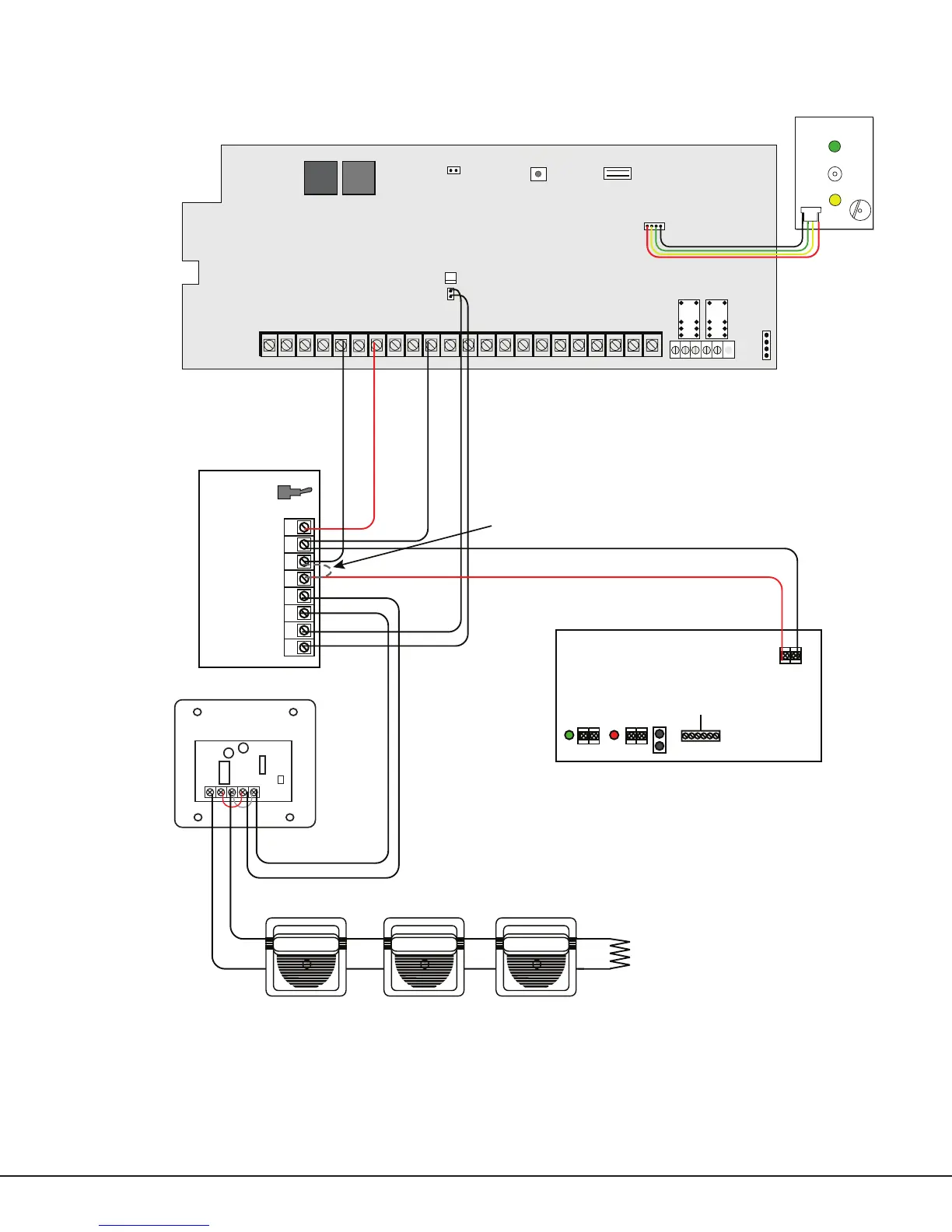
1 AUX PWR
2 GND
3 Alarm In
4 Bell PWR In
5 Bell Out +
6 Bell Out -
7 Bell Trouble
8 Bell Trouble
Normal/Silence Switch
Potter Model SNM
45mA @ 12 VDC
The SNM Notification
Appliance Circuit
Module in alarm draws
up to 31mA through its
Terminal 3 Alarm Input
and 45mA from its
Terminal 1 Aux Power
Input.
Panel Reset
AC
12 34
78
10 11 12 13 14 15 16
AC B+ B-
9
REDYEL GRNBLK Z1B- Z2 -Z2+
1
2
3
4
J12
Z1A- Z1B+Z1A+
PFC-7500 SeriesCommercial Fire Command
Processor Panel
MAINBACKUP
J11
N/C COM N/O N/C COM N/ O
Telephone Connections
J10 Trouble Annunciator Header
56
BELL SMK
OUTPUT 1
OUTPUT 2
SILENCE/RESET
PUSH FOR ONE SECOND
Silence/Reset
Button
Silence/Reset
Header
17 18
Z3 -Z3+
19 20
Z4 -Z4+
21 22
Z5 -Z5+
Bell
Monitor
r
J13
J14
Power Supply
J6
+ DC -
AC
Trouble
Batt
Trouble
J4
J3J2
Green
LED
AC
AC
+ BAT -
Red
LED
DC
12 VDC @ 5 Amps
Battery
Start
TAM Module
Auxiliary Power Supply must be regulated, power
limited, and listed for Fire Protective Signaling Service.
Power Supplies must have battery backup.
Note: If an auxiliary power supply is not used, terminals 3
and 4 can be jumpered together to supply Bell Power
from the panel.
The Auxiliary Power Supply and Notification Circuit
Module trouble contact zone must be programmed as
a Supervisory Type zone.
SM-12/24 Module
Polarized Notification
Appliances
10K EOLR
Sync module required
when using multiple
notification appliances
See the Notification Appliance
section for a list of appliances.
The maximum voltage drop between
the panel Bell Output and the EOLR is
.5 VDC when a separate power supply
is not used.
When using a separate power supply, the maximum
current is 3 Amps.
The Bell Output
programming for Fire type
zones must be set to
Steady.
Regulated 12
VDC