LED keypads to the panel and also connect control and annunciating devices to the panel Form C and annunciator
outputs. Refer to the Power Requirements section in this guide when calculating power requirements.
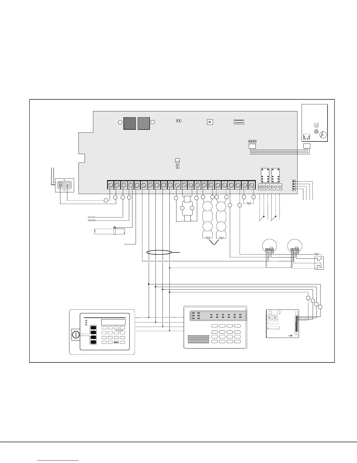
The PFC-7501 system below shows some of the accessory devices for use in various applications.
Pa nel Re s e t
RED
BLACK
GREEN
Ke ypad bus
22 gauge min.
BLACK
YELLOW
RED
Co ld Water Pi pe
Earth Gr ound
Output Header J1 1
Tw o Fo rm C (SPD T) Ou tputs.
Zone 2
AC
1234
78
10 11 12 13 14 15 16
AC B+ B-
9
REDYEL GRNBLK Z1B- Z2 -Z2+
1
2
3
4
J1 2
Z1A- Z1B+Z1A+
MODEL 7500
MAIN BA CKUP
J1 1
N/ C CO M N/ O N/ C CO M N/ O
Output Header J1 2
Fo ur Open Co llect or Outputs.
50mA at 30 VDC resi st ive
Re lay So ckets for Optional
Form C Outputs on J11
Requires Form C Relays
Telephone Co nnect ions
Zone 1
J10 Trouble Annunciator Header
S
S
Direct connect to
unsw itched 120 VAC 60 Hz
Secondary Po wer Su pply
12 VDC
1.2 Amps max. charging current.
Up to 500mA auxiliary
current at 12 VDC from
Terminal 7.
5 Zone LED Ke ypads
56
BELL SM K
Zone 4
Zone 5
Be ll Ci rcuit
Po wer
Su pervision
Re lay
(if code requires)
Ke ypad
Model RA-7692
30mA at 8 to 16 VDC
Ex pander
Model ZA714/ZA715
7mA at 12 VDC
+
3.3k
EOLR
+
Sm oke
Detect or
RED
BLACK
GROUND
Output 1Output2
OUTPUT 1
OUTPUT 2
SI LENCE/ RE SET
PU SH FOR ONE SECO ND
Si lence/R e se t
Button
Silence/ Re se t
Header
17 18
Z3 -Z3+
19 20
Z4 -Z4+
21 22
Z5 -Z5+
W
W
Up to 100mA of current is avai lable for
All zones are su pervised
4-wire sm oke detect ors from terminal 6.
Be ll Monitor
Zone 3
S
S
-
-
J1 3
Sm oke
Detect or
3.3k
EOLR
J1 4
TAM
Tr ouble
Annunciator
Module
16.5 VAC 40V A
wire-in transf ormer
3.3k
EOLR
Ke ypad
Model RA-7630
63mA at 8.5 to 14 VDC
POWER
TROUBLE
ALARM
COMMAND
1234
5678
90
ABC DEF GHI JKL
MNOPQR STU VWX
YX
ENABLE
SILENCE
RESET
TEST
DRILL
Fire Command Center
C1
C4
U1
U2
CR3
TXD
J1
R
E
D
Tens Ones
.6 Amps at 12 VDC
S
S
S
S
S
S
POWER LIMITED
All circuits on the Model PFC-7501 comply
with the requirements for inherent power
limitation and are Class 2 except the
red battery wire.
WARNING
THIS UNIT MAY BE PROGRAMMED TO USE AN ALARM
VERIFICATION FEATURE THAT RESULTS IN DELAY OF THE SYSTEM
ALARM SIGNAL FROM THE INDICATED CIRCUITS. THE TOTAL
DELAY (CONTROL UNIT PLUS SMOKE DETECTORS) SHALL NOT
EXCEED 60 SECONDS. NO OTHER SMOKE DETECTORS SHALL BE
CONNECTED TO THESE CIRCUITS UNLESS APPROVED BY THE
LOCAL AUTHORITY HAVING JURISDICTION.
S
S
S S
S S S S S
S S
S
S
S
S
S
USE MARKING
Co mmercial Pr otected
Pr emises Co ntrol Unit
TYPES OF SERVICE
Central Station DACT, Remote Station Signaling Service, Suitable for manual re
alarm, automatic re alarm, sprinkler supervisory or waterow alarm.
Model WLT
Use Model 300 Harness