Do you have a question about the Power Electronics VFD and is the answer not in the manual?
Guide to selecting the appropriate drive based on application requirements.
Explains why PE® drives do not require over-sizing for demanding applications.
Addresses compatibility with single-phase power sources and motors.
Details usage with two-speed motors and specific PE® drive models.
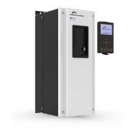
Guidance on correct vertical mounting and ventilation for optimal cooling.
Explains P.C. 22 flashing, indicating U22 parameter needs setting.
Procedure for resetting drive parameters to factory defaults for quick setup.
Details adjusting motor speed, acceleration, and deceleration using 'A' parameters.
Provides the unlock code required to access certain parameter groups.
Describes the four events that occur when a trip condition is detected.
Initial steps for troubleshooting, focusing on fuses, event codes, and memory.
Explains how event codes are automatically stored in diagnostic memory locations.
Guidance on interpreting event codes for diagnosing trip conditions.
Methods for clearing event codes and resetting the drive after a trip.
Explains F0 indicates no fault was stored or memory was cleared.
Troubleshooting steps for F1 (Current Trip), a common drive fault.
Addresses F1 trips occurring during acceleration and potential causes/solutions.
Addresses F1 trips occurring during deceleration and potential causes/solutions.
Addresses F1 trips at constant speed or when a specific speed is reached.
Addresses F1 trips when the motor doesn't start despite drive command.
Lists additional potential causes for F1 (Current Trip) faults.
Diagnosing F2 (Motor Thermal Trip) and I^2T trip events.
Troubleshooting F3 for braking resistor issues or low bus voltage.
Diagnosing F4 (Low Bus Voltage), a normal trip on power down.
Diagnosing F5 (Over Voltage Trip) and its causes like high input voltage.
Diagnosing F6/F7 (Auxiliary Trip) related to external device signals.
Diagnosing F8 (A Parameters Out of Spec) due to logical incompatibility.
Diagnosing F9 (CPU Error) indicating a failure of the drive's CPU.
Diagnosing F10 (Memory Error) due to parameter memory chip malfunction.
Diagnosing F11 (Timer) when motor runs longer than allotted time.
Diagnosing F12 (Hardware Failure) indicating internal component issues.
Diagnosing F13 (Overload) caused by overload device tripping.
Diagnosing F14 (Output Phase Loss) due to lost line to motor.
Diagnosing F17 (Encoder Tracking) when motor does not match drive command.
Diagnosing F18/F19 (Encoder Phase) for power loss in encoder wiring.
Diagnosing F20 (Heat Sink Too Hot) due to excessive drive temperature.
Diagnosing F21 (Brake Test Failure) indicating slipping during the test.
Diagnosing F22 (CPU Fault) indicating a failure of the drive's CPU.
Diagnosing F23 (Brake Control Circuit Open) due to wiring or fuse issues.
Diagnosing F24 (Drive Output Leads) for lost motor phase during start.
Diagnosing F25 (Extra Encoder Pulses) due to noise or incorrect settings.
Diagnosing F26 (Brake Relay Failure) indicating an internal brake control relay issue.
Diagnosing F27 (Weight Limit Trip) related to over-torque settings.
Diagnosing F28 (Power Supply Failure) affecting supplies, fans, or contactor.
Diagnosing F33 (Tracking Error) due to speed discrepancy with encoder feedback.
Diagnosing F34 (Encoder Tracking Error) during Zip-Up® function.
Diagnosing F35/F36 (Encoder Speed) for encoder running too fast.
Diagnosing F45 (Binding) after brake test failure, possibly slow DC brake reaction.
Diagnosing F46 (No Movement) when the encoder is not moving.
Diagnosing F47 (Encoder Problem) for missing encoder pulses.
The Power Electronics® Variable Frequency Drive (VFD) is a sophisticated device designed for precise control of three-phase motors, particularly in demanding applications such as electric overhead cranes and material handling. It offers advanced speed control, troubleshooting capabilities, and a robust design to handle various operational conditions.
The VFD's primary function is to convert single-phase line voltage to three-phase output for use with three-phase motors, or to directly control three-phase motors when three-phase power is available. It provides variable speed control, allowing for smooth acceleration and deceleration, which is crucial for applications requiring precise movement and reduced mechanical stress. The drive can be programmed to control either traverse motions (bridge, trolleys, rotation) or hoist motors, with specific models ("H" suffix) pre-programmed for hoist applications. For hoist motors, the VFD can integrate with mechanical load brakes or closed-loop systems using encoders for enhanced control and safety.
The VFD incorporates several protective features to ensure safe and reliable operation. It monitors motor current, temperature, and voltage, tripping out and displaying event codes (F-codes) when abnormal conditions are detected. This self-protection mechanism prevents damage to the drive and the motor. The device also includes brake outputs (B1 and B2) that open during a trip condition, bringing the crane motion to a stop using the brakes.
The VFD offers a range of user-configurable parameters to tailor its operation to specific application needs. These parameters are organized into groups (A, L, U, C, CL) for ease of navigation and adjustment.
The VFD is designed with troubleshooting and maintenance in mind, offering several features to assist users in diagnosing and resolving issues.
| Category | DC Drives |
|---|---|
| Manufacturer | Power Electronics |
| Control Method | Microprocessor-based control |
| Cooling Method | Forced air cooling |
| Protection Features | Overcurrent, overvoltage, undervoltage, short circuit, over temperature |