Rev. A 10/18
11
Application NoteAN-72
www.power.com
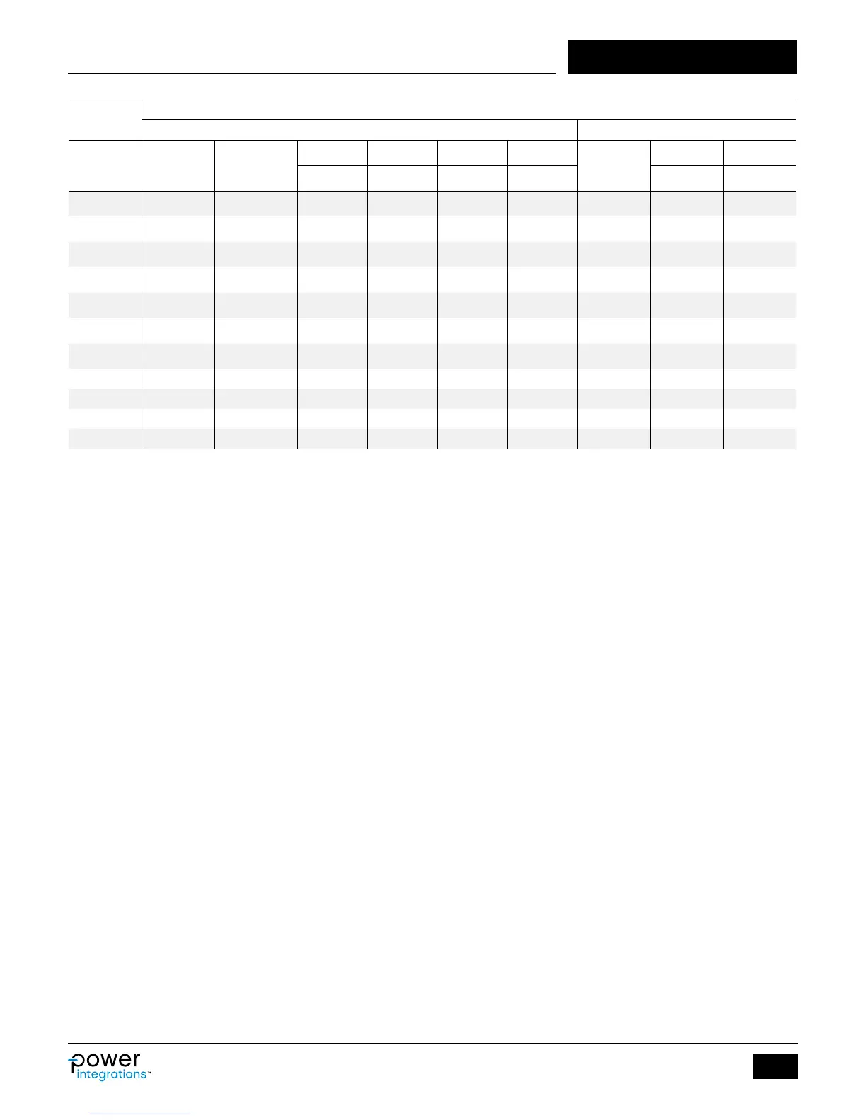
Table 7. Commonly Available Cores and Power Levels at Which These Cores Can be used for Typical Designs.
Core and Bobbin Table
Core Bobbin
Output
Power at
75 kHz
Core Code
AE LE AL VE
Code
AW BW
(mm
2
) (mm) (nH/T
2
) (mm
3
) (mm
2
) (mm)
0 W ‒ 10 W EE10
PC47EE10-Z
12.1 26.1 850 300 B-EE10-H 12.21 6.60
0 W ‒ 10 W EE13 PC47EE13-Z 17.1 30.2 1130 517 B-EE13-H 18.43 7.60
0 W ‒ 10 W EE16 PC47EE16-Z 19.2 35.0 1140 795 B-EE16-H 14.76 8.50
0 W ‒ 10 W EE19 PC47EE19-Z 23.0 39.4 1250 954 B-EE19-H 29.04 8.80
10 W ‒ 20 W EE22 PC47EE22-Z 41.0 39.4 1610 1620 B-EE22-H 19.44 8.45
10 W ‒ 20 W EE25 PC47EE25-Z 41.0 47.0 2140 1962 B-EE25-H 62.40 11.60
20 W ‒ 50 W EE30 PC47EE30-Z 111.0 58.0 4690 6290 B-EE30-H 13.20
0 W ‒ 10 W RM5 PC95RM05Z 24.8 23.2 2000 574 B-RM05-V 4.90
10 W ‒ 20 W RM6 PC95RM06Z 37.0 29.2 2150 1090 B-RM06-V 6.20
20 W ‒ 30 W RM8 PC95RM08Z 64.0 38.0 5290 2430 B-RM08-V 30.00 8.80
30 W ‒ 50 W RM10 PC95RM10Z 96.6 44.6 4050 4310 B-RM10-V 10.00
Safety Margin, MARGIN (mm)
For designs that require safety isolation between primary and
secondary, but are not using triple insulated wire the width of the
safety margin to be used on each side of the bobbin should be
entered here. Typically for universal (85 – 265 VAC) input designs a
total margin of 6.2 mm is required, and a value of 3.1 mm should be
entered into the spreadsheet. For vertical bobbins the margin may
not be symmetrical; however if a total margin of 6.2 mm is required
then 3.1 mm would still be entered even if the physical margin was
only present on one side of the bobbin. For designs using triple
insulated wire it may still be necessary to enter a small margin in
order to meet the required safety creepage distances. Typically
several bobbins exist for each core size and each will have different
mechanical spacing. Refer to the bobbin data sheet or seek guidance
to determine what specic margin is required.
Margin reduces the available area for the windings, marginated
construction may not be suitable for small core sizes. If after
entering the margin more than 3 primary layers are required, it is
suggested that either a larger core be selected or that the design is
switched to a zero margin approach using triple insulated wire.
Primary Turns, NPRIMARY
This is the number of turns for the main winding of the transformer
calculated based on VOR and Secondary Turns.
Peak Flux Density, BPEAK (Gauss)
A maximum value of 3800 gauss is recommended to limit the peak
ux density at max current limit and 132 kHz operation. Under an
output-shorted condition the output voltage is low and little reset of
the transformer occurs during the MOSFET off-time. This allows the
transformer ux density to “staircase” beyond the normal operating
level. A value of 3800 gauss at the max current limit of the selected
device together with the built in protection features of InnoSwitch3
provides sufcient margin to prevent core saturation under output
short-circuit conditions.
Maximum Flux Density, BMAX (Gauss)
The low frequency operation resulting from a light load condition can
generate audible frequency components within the transformer,
especially if a long core is used. To limit audible noise generation,
the transformer should be designed such that the maximum core ux
density is below 3000 gauss (300 mT). Following this guideline and
using the standard transformer production technique of dip varnishing
practically eliminates audible noise. A careful evaluation of the
audible noise performance should be made using production
transformer samples before approving the design.
AC Flux Density, BAC (Gauss)
The BAC value can be used for calculating core loss.
Gapped Core Effective Inductance, ALG: (nH/N
2
)
Used to specify the CORE GAP [LG].
Primary Layers, LAYERS_PRIMARY
By default, if the override cell is empty, a value of 3 is assumed.
Primary layers should be in the range of 1 ≤ L ≤ 3, and in general it
should meet the current capacity guideline of 200 – 500 circular mils/
ampere for designs without forced air cooling. Primary winding wire
gauge AWG_PRIMARY is calculated in cell [E82]. Values above 3
layers are possible but the increased leakage inductance and physical
t of the windings should be considered. A split primary construction
may be helpful for designs where leakage inductance clamp
dissipation is too high. In this approach half of the primary winding is
placed on either side of the secondary (and bias) windings in a
sandwich arrangement.
Primary Winding Wire Guage, AWG_PRIMARY (AWG)
By default, if the override cell is empty, double insulated wire is
assumed and a standard wire diameter is chosen. The grey override
cells can be used to enter the wire gauge directly by the user, or if
the wire used is different from the standard double insulated type.
 Loading...