Rev. A 10/18
12
Application Note AN-72
www.power.com
Secondary Turns, NSECONDARY
By default, if the grey override cell is left blank, the minimum number
of secondary turns is calculated such that the peak operating ux
density B
PEAK
is kept below the recommended maximum of 3800
gauss (380 mT). In general, it is not necessary to enter a number in
the override cell except in designs where a lower operating ux
density is desired.
Bias Turns, NBIAS
Determined based on VBIAS set voltage or secondary turns.
The other transformer parameters that are automatically calculated
by the spreadsheet include:
OD_PRIMARY_INSULATED (mm), Primary winding wire outer
diameter with insulation
OD_PRIMARY_BARE (mm), Outer diameter without insulation
CMA_PRIMARY (Cmil/A), Winding CMA
OD_SECONDARY_INSULATED (mm), Secondary winding wire
outer diameter with insulation
OD_ SECONDARY _BARE (mm), Outer diameter without insulation
CMA_ SECONDARY (Cmil/A), Winding CMA
Step 5 – Primary Components Selection
Enter: BROWN-IN VOLTAGE, VBIAS, VF_BIAS
Required Line Undervoltage Brown-in, BROWN-IN REQUIRED
This is the input AC voltage at which the power supply will turn on
(once the brown-in threshold (IUV+) is exceeded). The typical value
is 20% below minimum AC input voltage (VIN_MIN). The brown-in
voltage can be changed to a specic voltage required on cell [C101].
Line Undervoltage / Overvoltage Sense Resistor, RLS
PIXls will calculate the resistance value based on the brown-in
voltage. Shown as RLS1 + RLS2 on Figure 13, they are typically
connected after the bridge rectier. Typical total value for RLS1 +
RLS2 is 3.8 MΩ. RLS is approximately equal to V
BROWN-IN
× 1.414 / I
UV+
.
Brown-Out Actual
During brown-out, the power supply will inhibit switching when the
brown-out threshold current falls below the IUV- threshold.
Line Overvoltage, OVERVOLTAGE_LINE
This is the input AC voltage at which the power supply will
instantaneously stop switching once the overvoltage threshold (I
OV+
)
is exceeded, switching will be re-enabled when switching the line
overvoltage hysteresis (I
OV(H)
) level is reached. Line OV voltage is
approximately equal to I
OV+
× (RLS1 + RLS2) / 1.414.
Rectied Bias Voltage, VBIAS
A default value of 12 V is assumed. The voltage may be set to
different values (for example for applications when the bias winding
output is also used as a non-isolated primary-side auxiliary output).
Higher voltages typically increase no-load input power. Values below
10 V are not recommended since at light load there may be insufcient
voltage to supply current to the PRIMARY BYPASS pin which will
increase no-load input power. A 22 µF, 50 V low ESR electrolytic
capacitor is recommended for the bias winding rectication lter
capacitor, CBIAS. A low ESR electrolytic capacitor improves no-load
input power.
BPP Pin Capacitor, CBPP
The capacitance value is determined by the ILIMIT_MODE required.
0.47 µF for standard or 4.7 µF for increased current limit. Although
electrolytic capacitors can be used, often surface mount multi-layer
ceramic capacitors are preferred for use on double sided boards as
they enable placement of capacitors close to the IC. A ceramic X7R
(or better) type capacitor rated to at least 25 V is recommended.
Bias Diode Forward Drop, VF_BIAS
A default value of 0.7 V is used though this can be changed to match
the type of diode used for rectifying the bias winding.
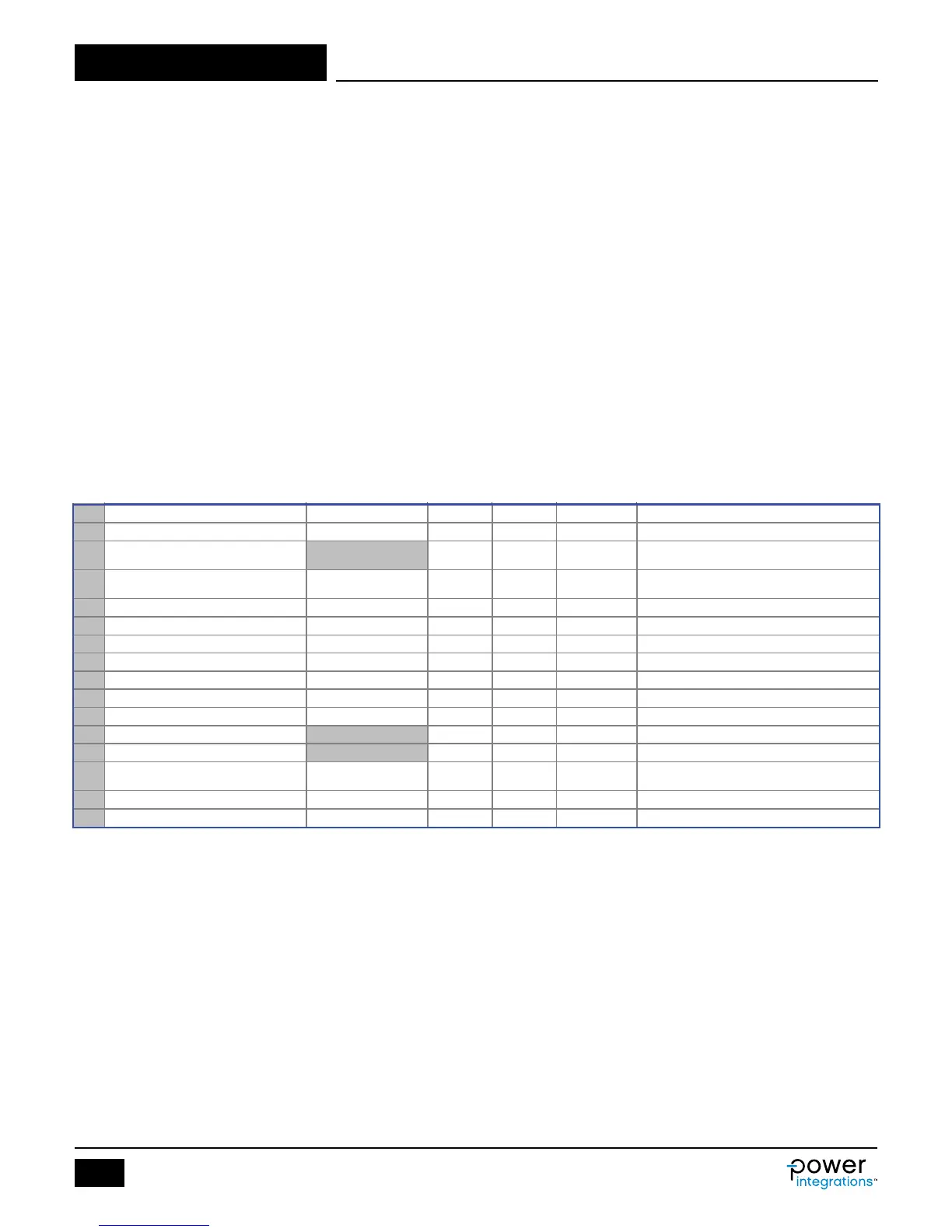
99 PRIMARY COMPONENTS SELECTION
101 BROWN-IN REQURED
74.0 V Required AC RMS line voltage brown-in threshold
Connect two 1.87 MOhm resistors to the V-pin for
the required UV/OV threshold
103 BROWN-IN ACTUAL 75.0 V Actual AC RMS brown-in threshold
104 BROWN-OUT ACTUAL 67.8 V Actual AC RMS brown-out threshold
106
107 OVERVOLTAGE_LINE 312.5 V Actual AC RMS line over-voltage threshold
109
110 VBIAS 12.0 V Rectified bias voltage
111 VF_BIAS 0.70 V Bias winding diode forward drop
112 VREVERSE_BIASDIODE 84.73 V
Bias diode reverse voltage (not accounting
parasitic voltage ring)
113 CBIAS 22 uF Bias winding rectification capacitor
114 CBPP 0.47 uF BPP pin capacitor
Figure 8. Primary Components Section of InnoSwitch3 PIXls Spreadsheet.