Rev. A 10/18
15
Application NoteAN-72
www.power.com
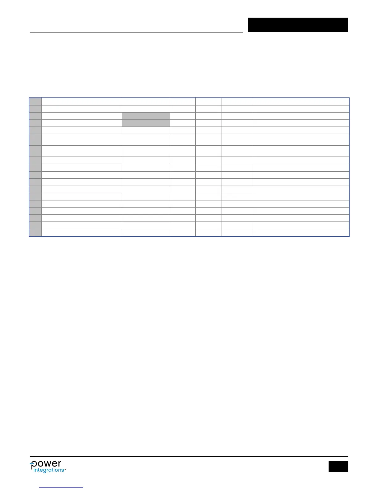
Figure 12. Tolerance Analysis Section of InnoSwitch3 PIXls Spreadsheet.
Step 8 ‒ Tolerance Analysis
This is a useful part of the InnoSwitch3 PIXls designer spreadsheet
that provides the user with switching parameters such as switching
frequency (FSWITCHING) for corner limits of device current limit
CORNER_ILIMIT and primary inductance of transformer
CORNER_LPRIMARY.
183 CORNER_VAC 85 V Input AC RMS voltage corner to be evaluated
184 CORNER_ILIMIT
0.95 A Current limit corner to be evaluated
185 CORNER_LPRIMARY TYP 830.5 uH Primary inductance corner to be evaluated
186 MODE_OPERATION CCM Mode of operation
187 KP 0.728
Measure of continuous/discontinuous mode of
operation
Switching frequency at full load and valley of the
rectified minimum AC input voltage
189 DUTYCYCLE 0.433 Steady state duty cycle
190 TIME_ON 6.44 us Primary MOSFET on-time
191 TIME_OFF 8.43 us Primary MOSFET off-time
192 IPEAK_PRIMARY 0.91 A Primary MOSFET peak currrent
193 IPEDESTAL_PRIMARY 0.25 A Primary MOSFET current pedestal
194 IAVERAGE_PRIMARY 0.25 A Primary MOSFET average current
195 IRIPPLE_PRIMARY 0.66 A Primary MOSFET ripple current
196 IRMS_PRIMARY 0.40 A Primary MOSFET RMS current
197 CMA_PRIMARY 252 Cmil/A Primary winding wire CMA
198 BPEAK 2835 Gauss Peak fux density
199 BMAX 2641 Gauss Maximum flux density