Rev. A 10/18
5
Application NoteAN-72
www.power.com
The capacitance is used to calculate the minimum and maximum DC
voltage across the bulk capacitor and should be selected to keep the
minimum DC input voltage, VMIN > 70 V.
Nominal Output Voltage, VOUT (V)
Enter the nominal output voltage of the main output at full load.
Usually the main output is the output from which feedback is derived.
Cable Compensation, PERCENT_CDC (%)
Select the appropriate cable compensation depending on the choice
of cable for the design. If this power supply is not supplied with a
cable, use the default 0%. (For InnoSwitch3-EP, this feature is not
available)
Power Supply Output Current, IOUT (A)
This is the maximum continuous load current of the power supply.
Output Power, POUT (W)
This is a calculated value and will be automatically adjusted based on
cable compensation selected.
Power Supply Efciency, EFFICIENCY (η)
Enter the estimated efciency of the complete power supply
measured from the input and output terminals under peak load
conditions and worst-case line (generally lowest input voltage). The
table below can be used as a reference. Once a prototype has been
constructed then the measured efciency should be entered and
further transformer iteration(s) can be performed if required.
Power Supply Loss Allocation Factor, FACTOR_ Z
This factor describes the apportioning of losses between the primary
and the secondary of the power supply. Z factor is used together
with the efciency to determine the actual power that must be
delivered by the power stage. For example losses in the input stage
(EMI lter, rectication etc) are not processed by the power stage
(transferred through the transformer) and therefore although they
reduce efciency the transformer design is not effected.
TotalLosses
Secondary Losses
Z =
For designs that do not have a peak power requirement, a value of
0.5 is recommended. For designs with a peak power requirement
enter 0.65. The higher number indicates larger secondary side
losses.
Enclosure
Power device selection will also be dependent on the application
environment. For an open frame application where the operating
ambient temperature is lower than in an enclosed adapter, the PIXls
will suggest a smaller device for the same output power.
Efciency is also a function of output power, low power designs are
most likely around 84% to 85% efcient, whereas with a synchronous
rectier (SR) the efciency would reach 90% typically.
Nominal Output
Voltage (VOUT)
Typical Low-Line Range Typical Universal Range Typical High-Line Range
85 VAC - 132 VAC 85 VAC - 265 VAC 185 VAC - 265 VAC
Schottky Diode
Rectier
Synchronous
Rectier
Schottky Diode
Rectier
Synchronous
Rectier
Schottky Diode
Rectier
Synchronous
Rectier
5 0.84 0.87 0.84 0.88 0.87 0.89
12 0.86 0.90 0.86 0.90 0.88 0.90
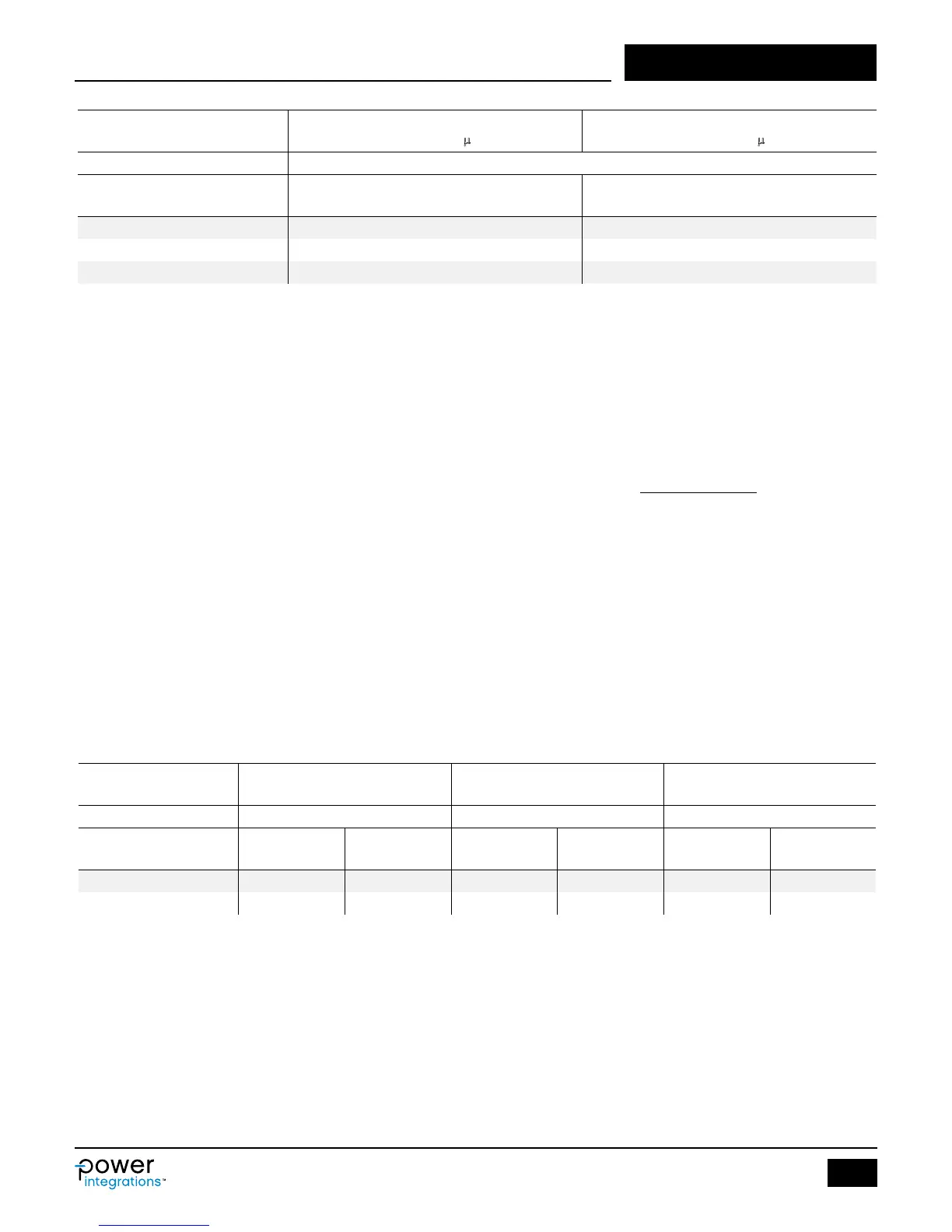
Total Input Capacitance per Watt of
Output Power (µF/W)
Total Input Capacitance per Watt of
Output Power (µF/W)
AC Input Voltage (VAC) Full Wave Rectication
Adapter with hold-up time requirement
Open Frame or Charger/Adapter without
hold-up time requirement
100 / 115 3 2
230 1 1
85-265 3 2
Table 4. Efciency Estimate Without Output Cable .
Table 3. Suggested Total Input Capacitance for Different Input Voltage Ranges.