Rev. A 10/18
6
Application Note AN-72
www.power.com
Step 2 – Primary Controller Selection
Enter: Device Current Limit mode, ILIMIT and Generic Device
Code, DEVICE_GENERIC
Generic Device Code, DEVICE_GENERIC
The default option is automatically selected based on input voltage
range, maximum output power and application (i.e. adapter or open
frame).
For manual selection of device size, refer to the InnoSwitch3 power
table in the data sheet and select a device based on the peak output
power. Then compare the continuous power to adapter column
numbers in the power table, (if the power supply is of fully enclosed
type), or compare to the open-frame column (if the power supply is
an open-frame design). If the continuous power exceeds the value
given in the power table (Table 1), then the next larger device should
be selected. Similarly, if the continuous power is close to the
maximum adapter power given in the power table, it may be
necessary to switch to a larger device based on the measured
thermal performance of the prototype.
Device Current Limit Mode, ILIMIT_MODE
For designs where thermals are not as challenging (such as open
frame applications) and lowest cost is a critical requirement, ILIMIT
MODE allows the choice of an INCREASED current limit mode, this
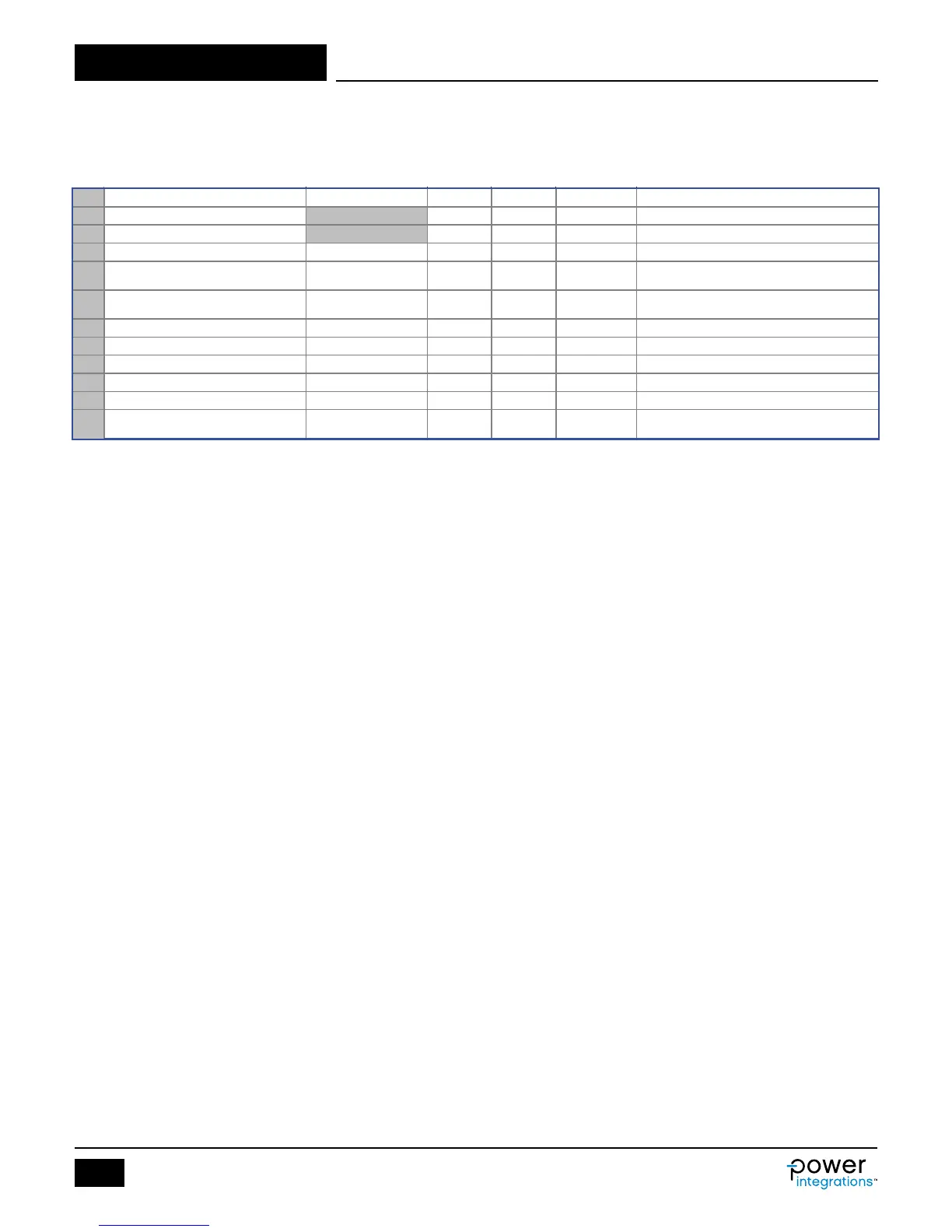
Figure 3. Primary Controller Selection of InnoSwitch3-CE Design Spreadsheet with Current Limit Mode Selection.
18 PRIMARY CONTROLLER SELECTION
19 ILIMIT_MODE STANDARD STANDARD Device current limit mode
20 DEVICE_GENERIC
INN31X5 Generic device code
21 DEVICE_CODE INN3165C Actual device code
22 POUT_MAX 22 W
Power capability of the device based on thermal
performance
Primary MOSFET on time drain resistance at 100
degC
24 ILIMIT_MIN 0.88 A Minimum current limit of the primary MOSFET
25 ILIMIT_TYP 0.95 A Typical current limit of the primary MOSFET
26 ILIMIT_MAX 1.02 A Maximum current limit of the primary MOSFET
27 VDRAIN_BREAKDOWN 650 V Device breakdown voltage
28 VDRAIN_ON_MOSFET 0.87 V Primary MOSFET on time drain voltage
29 VDRAIN_OFF_MOSFET 508.4 V
Peak drain voltage on the primary MOSFET
during turn-off
will set the peak current of the device equivalent to the next bigger
device’s current limit and allow higher output power. By default,
ILIMIT is set to STANDARD.
On-Time Drain Voltage, VDRAIN_ON_MOSFET (V)
This parameter is calculated based on RDSON_100DEG and primary
RMS current.
Drain Peak Voltage, VDRAIN_OFF_MOSFET (V)
This parameter is the assumed Drain voltage seen by the device
during off-time. The calculation assumes 10% minimum margin from
the breakdown voltage rating of the internal MOSFET and gives a
warning if this is exceeded.
VDRAIN < (VIN_MAX * 1.414) + VOR + VLK
PRI
– (BV
DSS
× 10%).
VLK
PRI
is the voltage induced by the leakage inductance of the
transformer when MOSFET turns off.
Other electrical parameters are displayed based from the data sheet,
RDSON_100DEG, ILIMIT_MIN, ILIMIT_TYP, ILIMIT_MAX,
VDRAIN_BREAKDOWN.