Rev. A 10/18
7
Application NoteAN-72
www.power.com
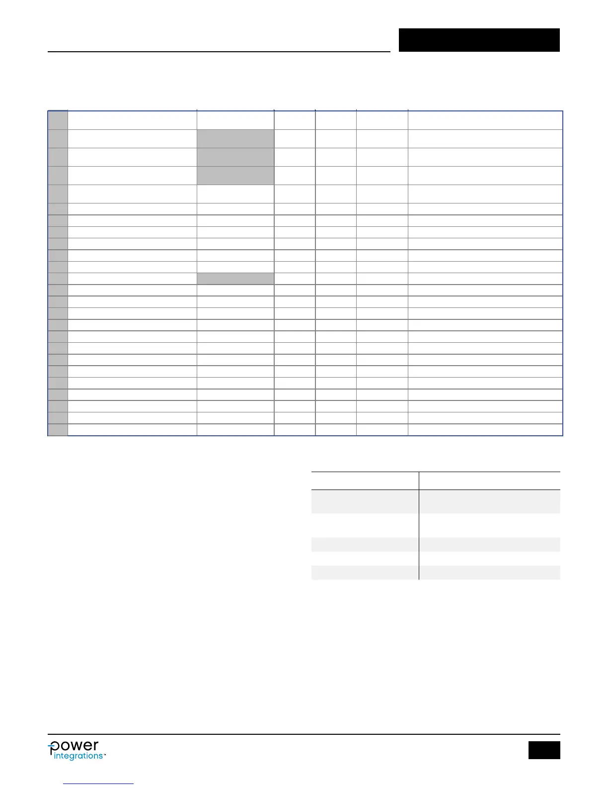
Figure 4. Worst-Case Electrical Parameters Section of InnoSwitch3-CE Design Spreadsheet with Gray Override Cells.
Table 5. Suggested Maximum Switching Frequency.
33
PARAMETERS
34 FSWITCHING_MAX 80000 80000 Hz
Maximum switching frequency at full load and
valley of the rectified minimum AC input voltage
35 VOR 65.0 V
Seconday voltage reflected to the primary when
the primary MOSFET turns off
Valley of the rectified minimum AC input voltage
at full power
37 KP 0.66
Measure of continuous/discontinuous mode of
operation
38 MODE_OPERATION CCM Mode of operation
39 DUTYCYCLE 0.433 Primary MOSFET duty cycle
40 TIME_ON 7.46 us Primary MOSFET on-time
41 TIME_OFF 7.09 us Primary MOSFET off-time
42 LPRIMARY_MIN 805.6 uH Minimum primary inductance
43 LPRIMARY_TYP 830.5 uH Typical primary inductance
44 LPRIMARY_TOL
3.0 % Primary inductance tolerance
45 LPRIMARY_MAX 855.4 uH Maximum primary inductance
46
47 PRIMARY CURRENT
48 IPEAK_PRIMARY 0.95 A Primary MOSFET peak currrent
49 IPEDESTAL_PRIMARY 0.30 A Primary MOSFET current pedestal
50 IAVG_PRIMARY 0.25 A Primary MOSFET average current
51 IRIPPLE_PRIMARY 0.76 A Primary MOSFET ripple current
52 IRMS_PRIMARY 0.41 A Primary MOSFET RMS current
53
55 IPEAK_SECONDARY 12.24 A Secondary winding peak current
56 IPEDESTAL_SECONDARY 3.79 A Secondary winding current pedestal
57 IRMS_SECONDARY 6.44 A Secondary winding RMS current
Step 3 – Worst-Case Electrical Parameters
Enter: FSWITCHING_MAX, VOR and LPRIMARY_TOL, or VMIN
Switching Frequency, FSWITCHING_MAX (Hz)
This parameter is the switching frequency at full load at minimum
rectied AC input voltage. The maximum switching frequency of
InnoSwitch3 in normal operation is 100 kHz, and the typical overload
detection frequency of is 110 kHz. In normal operating condition, the
switching frequency at full load should not be close to the overload
detection frequency.
The programmable switching frequency range is 25 to 95 kHz, but it
should be continued that the average frequency accounting for
primary inductance and peak current tolerances does not result in
average frequency higher than 110 kHz as this will trigger auto-
restart due to overload. Pushing frequency higher to reduce
transformer size is advisable, but Table 5 provides the suggested
frequency based on the size of the internal high-voltage MOSFET, and
represents the best compromise to balance overall device losses (i.e.
conduction and switching losses).
Reected Output Voltage, VOR (V)
This parameter is the secondary winding voltage during the diode /
Synchronous Rectier MOSFET (SR FET) conduction-time reected
back to the primary through the turns ratio of the transformer. Table
6 provides suggested values of VOR. VOR can be adjusted to achieve
a design that does not violate design rules for the transformer and
InnoSwitch3 Family Maximum Switching Frequency
INN3xx2C and
INN3xx3C
85 - 90 kHz
INN3xx4C and
INN3xx5C
80 kHz
INN3xx6C 75 kHz
INN3xx7C 70 kHz
INN3xx8C 65 kHz
SR FET while simultaneously achieving sufciently low Drain-Source
voltage of the primary side MOSFET. VOR can be adjusted as
necessary to ensure that no warnings in the spreadsheet are
triggered. For design optimization purposes, the following factors
should be considered,
• Higher VOR allows increased power delivery at VMIN, which
minimizes the value of the input capacitor and maximizes power
delivery from a given.