Rev. A 10/18
8
Application Note AN-72
www.power.com
• Higher VOR reduces the voltage stress on the output diodes and SR
FETs, which in some cases may allow a lower voltage rating for
higher efciency.
• Higher VOR increases leakage inductance which reduces power
supply efciency.
• Higher VOR increases peak and RMS current on the secondary-side
which may increase secondary side copper, diode and SR FET losses
thereby reducing efciency.
It should be noted that there are exceptions to this guidance
especially for very high output currents where the VOR should be
reduced to obtain highest efciency. Higher output voltages
(above 15 V) should employ a higher VOR to maintain acceptable
peak inverse voltage (PIV) across the output SR FET.
Optimal selection of the VOR value depends on the specic
application and is based on a compromise between the factors
mentioned above.
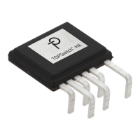
Mode of Operation, K
P
K
P
is a measure of how discontinuous or continuous the mode of
switching is. K
P
> 1 is said to be in discontinuous operation (DCM),
while K
P
< 1 denotes continuous operation (CCM).
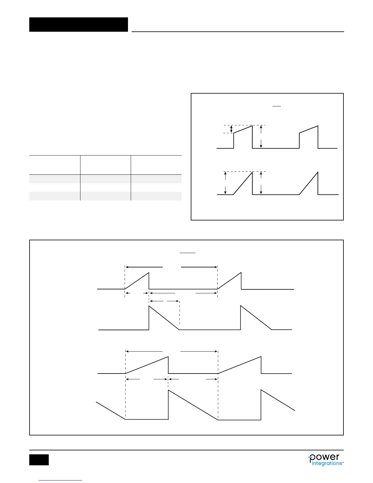
Ripple to Peak Current Ratio, K
P
Below 1 (indicating continuous conduction mode), K
P
is the ratio of
ripple to peak primary current (Figure 5).
Table 6. Suggested Values for VOR.
Figure 5. Continuous Mode Current Waveform, K
P
≤1.
Output
Voltage
Suggested VOR
Value
Suggested
Range
5 V 55 V 45 V - 60 V
9 V 85 V 80 V - 90 V
12 V - 20 V 110 V 100 V - 120 V
K
P
≡ K
RP
=
(a) Continuous, K
P
< 1
(b) Borderline Continuous/Discontinuous, K
P
= 1
I
R
I
P
I
PI
R
I
P
I
R
PI-2587-103114
Primary
Primary
K
P
≡ K
DP
=
T = 1/f
S
T = 1/f
S
(1-D) × T
(1-D) × T = t
t
D × T
D × T
(b) Borderline Discontinuous/Continuous, K
P
= 1
(a) Discontinuous, K
P
> 1
Primary
Secondary
Primary
Secondary
PI-2578-103114
(1-D) × T
t
Figure 6. Discontinuous Mode Current Waveform, K
P
≥1.