11
Replacing the Communications Card
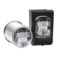
1. Remove the meter’s cover and shield by following the steps outlined in
“Accessing the Socket Meter’s PC Boards” on page 7.
2. Remove display board by gently prying tabs back, pulling straight up on
the display board.
NOTE
Attempting to remove the Display unit at an angle will damage its connector
on the CPU.
3. Slide out the I/O card, exposing the communications board.
4. Disconnect all wire plugs at the front end of the card by lifting locking tabs
with a fine point tool. Slide card out.
5. Insert new communications board and connect wires in their
corresponding sockets.
6. Re-insert the I/O card if applicable and the display board.
7. Re-place the cover with the four side screws (taking care not to pinch any
of the wiring) and connect the ground wire.
8. Re-insert the shield with its two screws.
9. Re-insert the cover by aligning the rim slots and press down, twisting
clockwise. Secure with new base seal provided.
 Loading...