Power Probe IV
www.powerprobe.com · 800-655-3585
Page 4
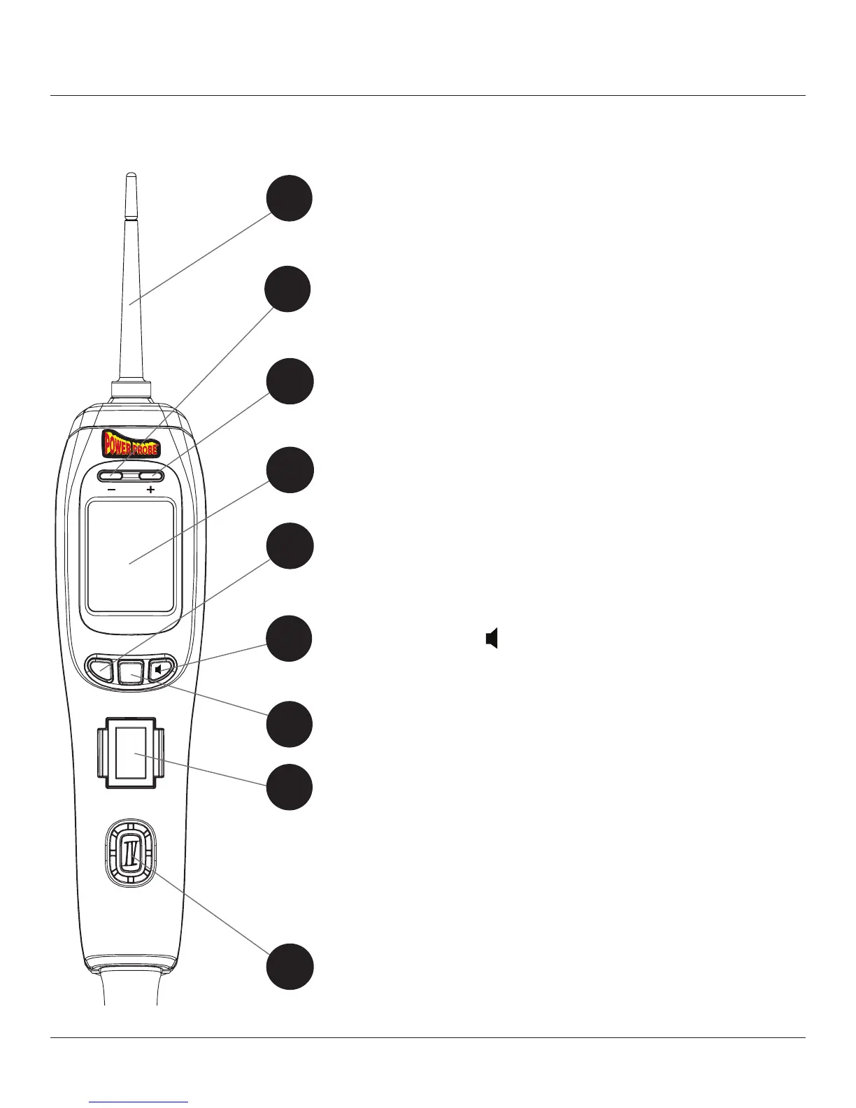
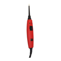
Appearance and Controls
H
J
H
J
Removable Probe Tip -Uses standard 4mm banana
type connector enabling use of different probes, leads,
or extensions.
LED, Green (-) -Will light indicating a path to ground.
More than10Ω resistance and/or more than 0.5 volts
on a ground circuit, the Green LED will not illuminate.
Button, Right; “ ” Mute / Scroll Down - Used to
turn the Speaker Tone On/Off or “Scroll Down” when
navigating menus.
2
LED, Red (+) -Will light indicating (B+) Battery pos-
itive. If the circuit voltage drop is more than 0.5 volts
from battery voltage, the Red LED will not illuminate.
3
Color Screen - Large Hi-resolution LCD display shows
multiple readings on one screen.
4
Button, Left; “CLR” Clear / Scroll Up - Used to
clear Min/Max in voltmeter modes or “Scroll Up”
when navigating menus.
5
6
Button, Center; “MODE” Select - Used to select a
test mode when navigating menus.
7
Rocker Switch (replaceable) Part #30-00087 -
When rocker switch is pressed forward(+) battery pow-
er(B+) is applied to the probe tip. When rocker switch
is pressed rearward(-) battery ground(B-) is applied to
the probe tip. Can only be used when in either of the
DC voltmeter modes.
8
Speaker - Distinct tones for power(B+) or ground(B-)
9
1
MODE
CLR