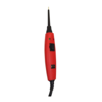
Power Probe IV
www.powerprobe.com · 800-655-3585
Start-Up
Operating Source Voltage
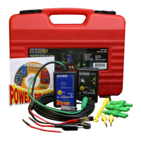
The Power Probe IV is designed
to connect to and is powered by
12 to 24 VDC electrical systems
and comes supplied with a 23 ft.,
heavy duty power cable and a
Y-connector with 2 battery clips.
Connecting to the Vehicle’s
Battery (Voltage Source)
Connect the red clip to the positive
terminal of the vehicle’s battery
source and the black clip to the
negative or ground terminal. The
Power Probe IV start-up tone will
sound.
Auxiliary Ground Lead
The auxiliary ground lead provides
ground to circuits and components
that are not already connected to
ground. It also serves as the neg-
ative lead for resistance testing. To
test the auxiliary ground lead, con-
tact the probe tip and the auxiliary
ground lead together. The Green
LED should illuminate. This shows
that the auxiliary ground lead
is working properly. If the green
LED does not illuminate, check the
replaceable 20 amp fuse in the
auxiliary ground lead. The fuse
is for protection in the event the
ground lead inadvertantly contacts
the battery positive.
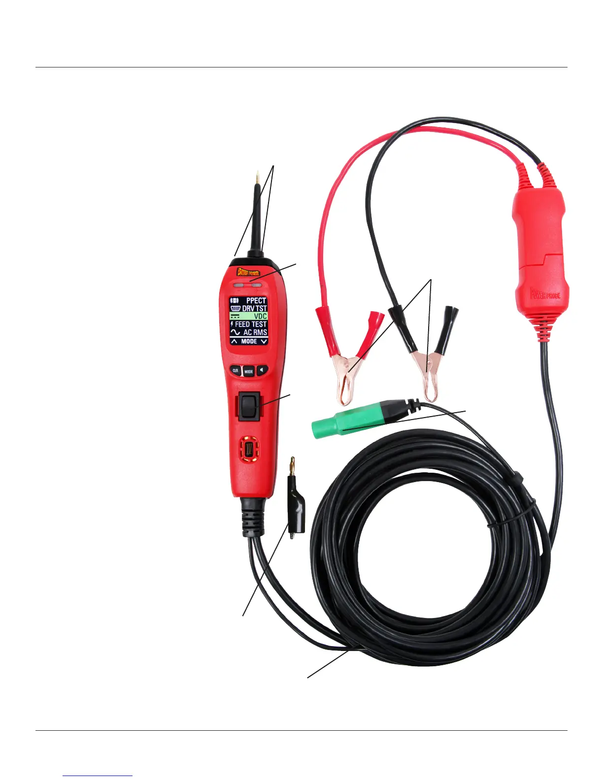
LED Flashlight
Flashlight is a standard feature on
the Power Probe IV. The two bright
white LEDs are always ON mak-
ing it possible to see under dash-
boards and in dark areas.
Flashlight
23 ft. Power
Lead
Battery Clips
Auxiliary
Ground
Lead
Page 6
Red/Green
LEDs
Rocker
Switch
Alligator Clip
Adapter