CHAPTER 5 — OPERATION FOR PLC-7420 CONTROL SYSTEM
5.4.2 Remote Operation
The genset can be set remote control function.
Connecting to the remote control switch by 9 or 4
pin communication connector realizes remote start
and stop.
NOTE: Remote start and AMF functions can only
be applied separately.
•Settingremotecontrolswitch
1)Connecttheremotecommunicationline(ifap-
plied)tothecommunicationconnectoronthe
genset.
2)Makearemotestartswitchthroughconnecting
thecorrespondingterminalsintheotherendof
communicationlinewithsuitablewirings.The
usercandistributethewiringaccordingtothe
gensetwiringdiagram.
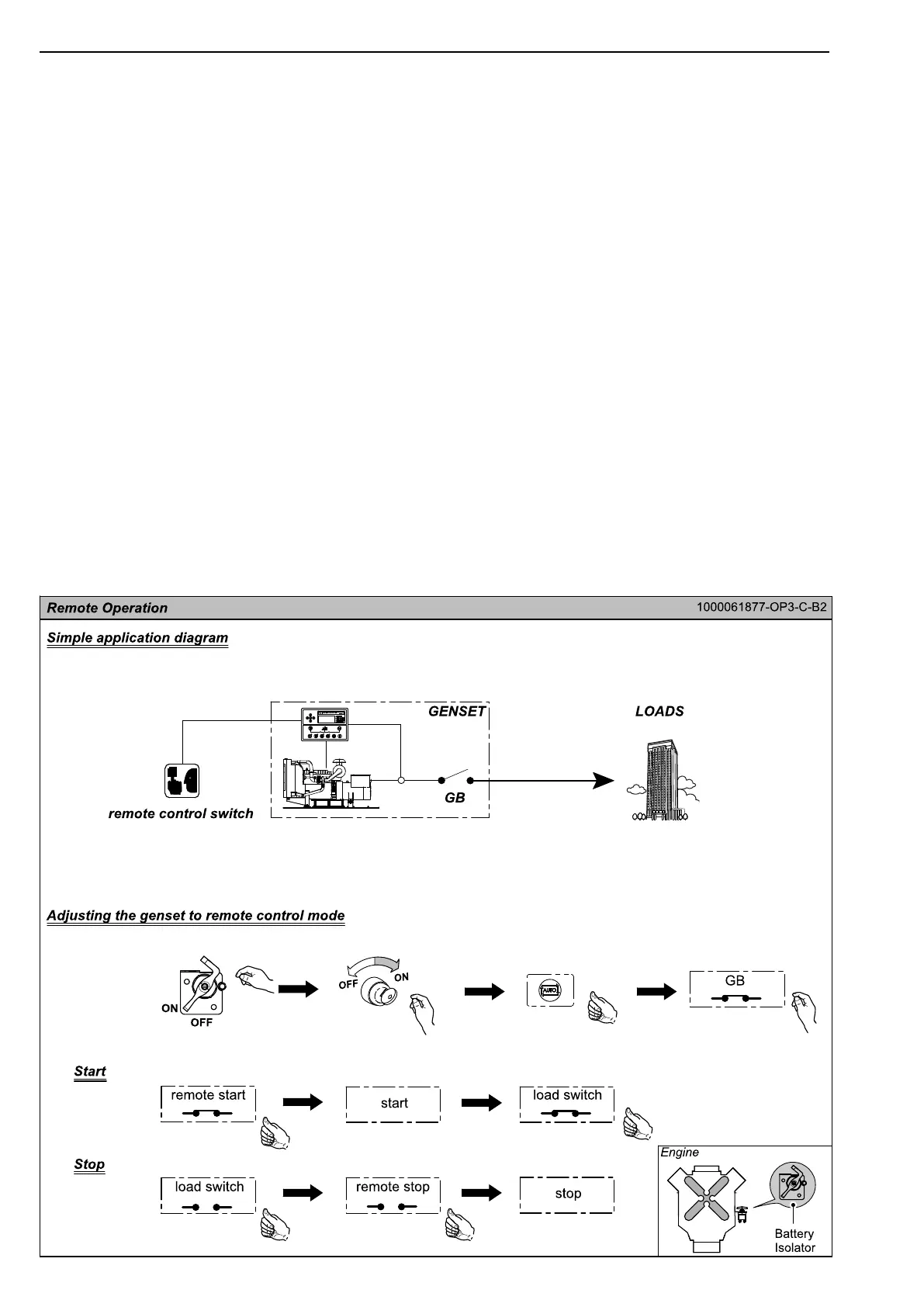
•Adjustingthegensettoremotecontrolmode
1)TurntheBatteryIsolatorto"ON".
2)TurntheKeySwitchto"ON".
3)PressAutoModeButton.ItsLEDilluminates.
4)SwitchontheGensetMainCircuitBreaker.
•OperationInstruction
(1)Start
1)PresstheRemoteStartButton.
2)Whenthecontrolmodulereceivesremotestart
signal,itwillperformtheautostartsequence.
3)Afterthegensetstartssuccessfully,switchonev-
eryswitchofloads(fromheavytolowinse-
quence).Thegensetwillexportpowertoload.
(2)Stop
1)Shutoffallswitchesandcircuitbreakersofloads
(fromlowtoheavyinsequence).
2)PresstheRemoteStopButton.
3)Theenginekeepsidlinguntilcoolingtimeisover.
Thenitstops.
Inaddition,connecting9pinconnectortoATS
controlcabinetcanrealizetotransferautomatically
thepowersupplyofloadsbetweenthemainsand
genset.Referto“ATSControlCabinetOperation
Manual”fordetails.
32