LIMIT ADJUSTMENT PROCEDURE
▲ WARNING: READ ENTIRE PROCEDURE BEFORE
STARTING. TURN OFF MAIN POWER BEFORE MAKING
ANY ADJUSTMENTS!
▲ WARNING: STAY CLEAR OF ALL MOVING PARTS AND
ELECTRICAL COMPONENTS OF THE OPERATOR WHILE
TESTING!
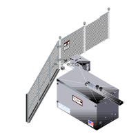
A CONTROL STATION SUCH AS A THREE BUTTON
STATION (“OPEN”,”CLOSE”,“STOP”) WITH ALL
NORMALLY OPEN CONTACTS IS REQUIRED FOR THIS
PROCEDURE. SEE INSTRUCTIONS BELOW.
456
7
OPEN
CLOSE
STOP
COMMON
1. Connect a wire from the common connection of the
control station to terminal #5.
2. Connect a second wire from the “OPEN” button of
the control station to terminal #6.
3. Connect a third wire from the “CLOSE” button of the
control station to terminal #7.
4. Connect a fourth wire from the “STOP” button of the
control station to terminal #4.
24
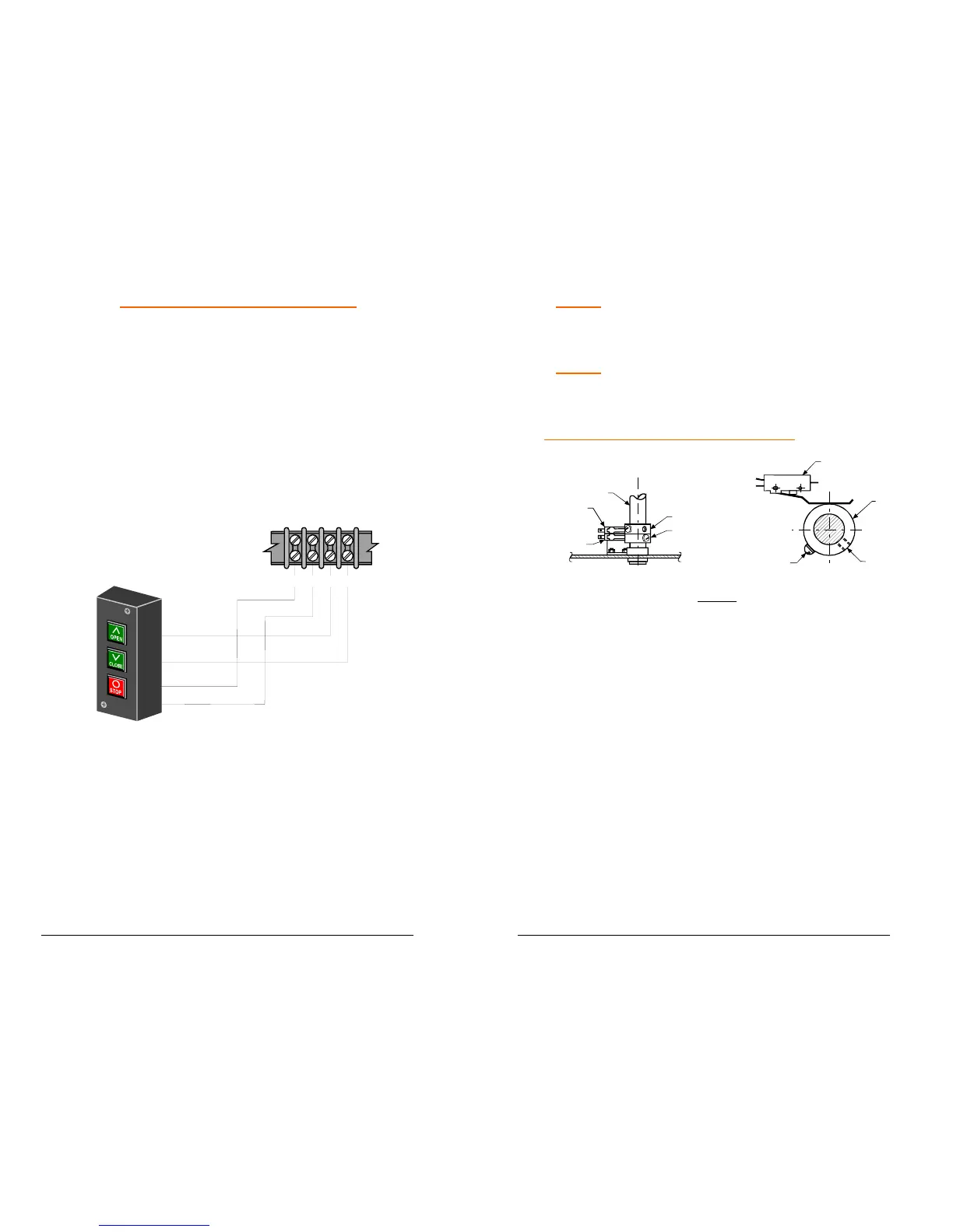
NOTE: Operator should be completely installed,
mechanically and electrically, before attempting to
set limit switch cams (See Fig. 11).
NOTE: For master slave installation, travel time for
the master operator must be set longer than the
slave operator.
OPEN LIMIT SWITCH ADJUSTMENT:
Figure 11
ADJUSTMENT
SET SCREW
LIMIT CAM
OPEN LIMIT CAM
CLOSE LIMIT CAM
DRIVE SHAFT
OPEN LIMIT SWITCH
CLOSE LIMIT SWITCH
LIMIT SWITCH
ACTUATING SCREW
1. Turn on power. Press open button on control station,
gate should stop before full open position is reached. If
gate does not stop when open position is reached,
PRESS STOP BUTTON!
2. To adjust gate for more open travel, loosen open limit
cam set screw and rotate limit cam, in the opposite
direction drive shaft rotates to open gate. Re-tighten set
screw after adjustment (See Fig. 11).
3. If it was necessary to stop gate, adjust open limit
switch cam for less open travel, by rotating the cam in
the same direction that the drive shaft rotates to open the
gate.
4. Press close button and stop gate in mid travel with
stop button.
5. Repeat procedure until desired open setting is
obtained.
 Loading...