SECONDARY OBSTRUCTION SENSING DEVICES
Another sensing device (Either a contact or a non-contact
system) must be installed and connected to this unit to
increase protection against entrapment per U/L requirements.
NOTE: All safety device contacts must be NORMALLY OPEN.
NOTE: 24 VAC power is available at marked terminals for
devices that may require it (
i.e., photo eyes, wireless edges, etc).
CONTACT SENSOR INSTALLATION:
NOTE: When wireless sensors are installed it must be done so
there is no signal interference.
NOTE: All hard wiring to safety edges must be installed so
there is no threat of mechanical damage to wiring between
components, when the gate is moving.
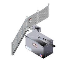
1. Install electric edge sensors in locations shown below.
NOTE:
A separate pedestrian gate must be installed if there is
no other entry access but the vehicular gate.
Electric Edge
Mounted On
Vertical Outside
Edge Of Gate
Horizontal Electric
Edge Mounted
On Inside Bottom
Of Gate
Horizontal
Electric Edge
Mounted
On Outside Bottom
Of Gate
36
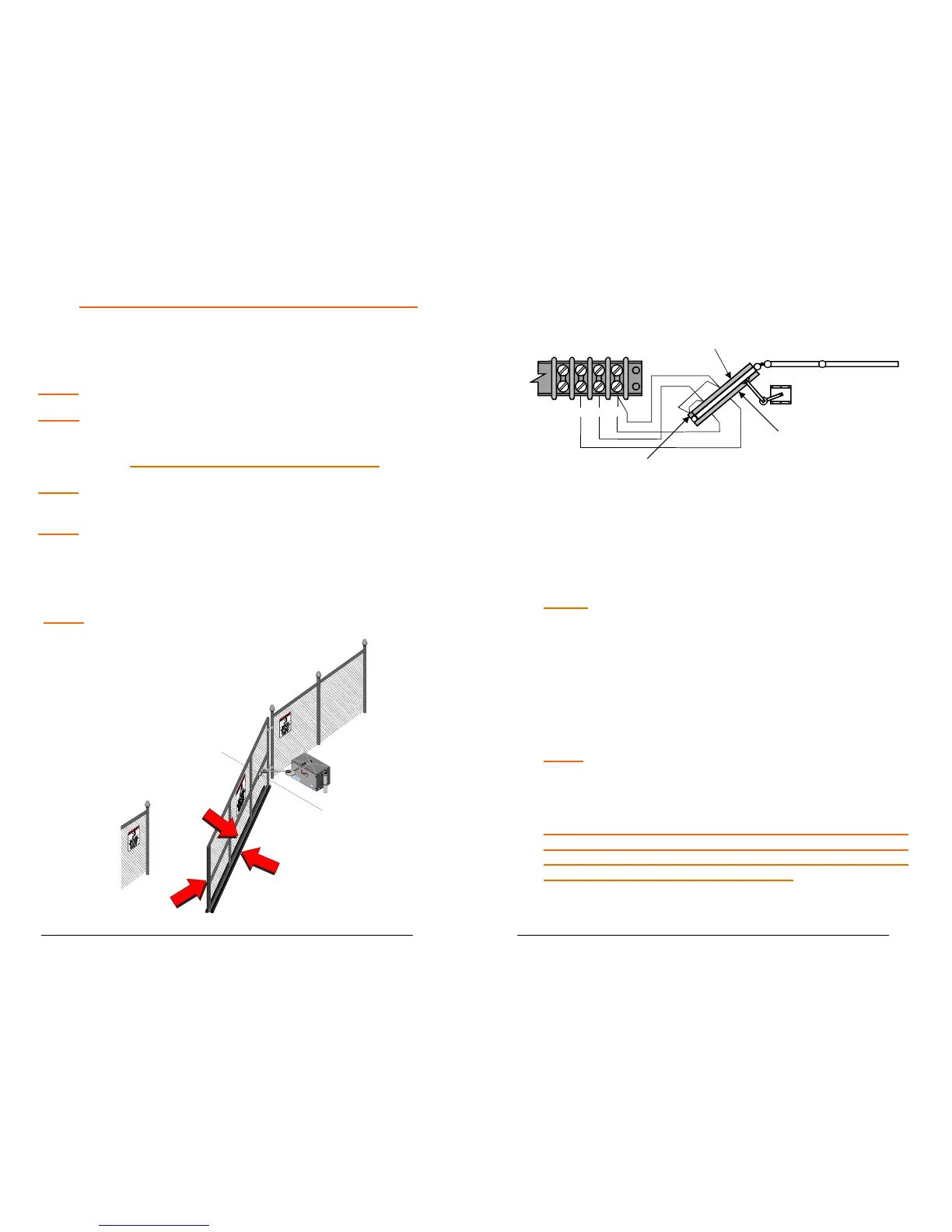
2. Connect contact sensor edges to the control board as
shown in the illustration below.
11 12
13 14
Vertical Edge
Inside Edge
Outside Edge
3. After sensors are mounted and electrically connected,
turn on the power.
4. Test the close obstruction sensing system for proper
operation, by depressing the vertical edge sensing
strip while the operator is running closed.
NOTE: The operator should stop and reverse a short
distance and then stop.
5. Run the operator to the open limit, and repeat step #3
for the outside horizontal edge.
6. Test the open obstruction sensing system by
depressing the inside horizontal edge sensor while
the gate is opening.
NOTE: The operator should repeat the STOP AND
REVERSE procedure.
NOTE: If an edge is activated twice or a second edge is
activated before a limit is hit (full open or close) operator
will stop and sound a warning horn. To reactivate system
turn operator power switch off, then on.
 Loading...