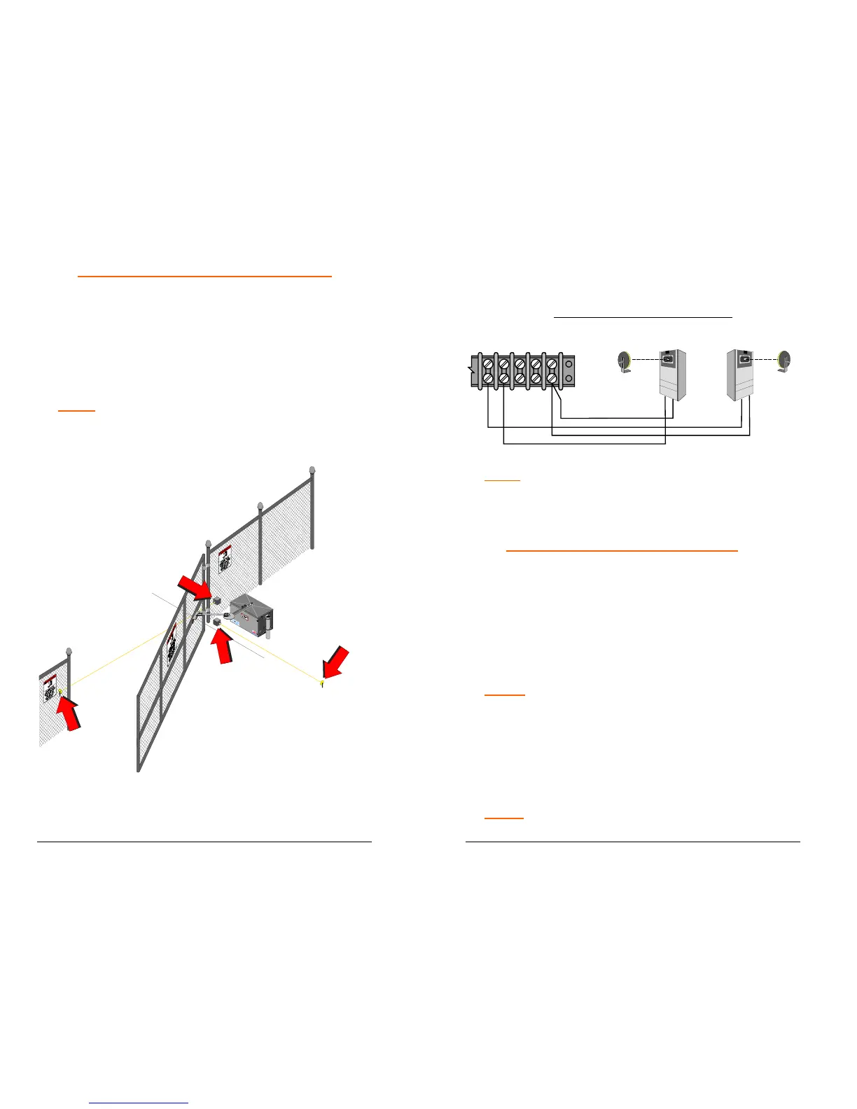
NON-CONTACT SENSOR INSTALLATION
1. Install photoelectric cell as close to the full open
position and full closed position of gate as possible.
2. Photocells should be installed across the gate
opening and behind the gate (as shown below) at
least 10 inches above ground.
NOTE:
A separate pedestrian gate must be installed if
there is no other entry access but the vehicular gate.
Photo Electric Cell
(For Open Direction)
Photo Electric Cell
( For Close Direction)
Photo Electric
Reflector (Mount
Past Gates Full
Close Position )
Photo Electric Reflector
(Mount Past Gates Full
Open Position )
38
3. Connect NON-CONTACT sensors to the control board
as shown below.
NON CONTACT SENSOR CONNECTION
Close Photocell
Sensor
Open Photocell
Sensor
Align With
Reflector
Align With
Reflector
10 11 12 13 14
Reflector Reflector
NOTE: Close photocell is connected to terminal #11 and
terminal #14. Open photocell is connected to terminal #10
and terminal #14.
AFTER SENSORS ARE CONNECTED:
1. Turn on power.
2. Make sure the photo-beams are properly aligned per
the manufacturer’s specifications.
3. Test the CLOSE obstruction sensing system for proper
operation, by blocking the beam across the gate
opening while the gate is running closed.
NOTE: The gate should stop and reverse a short distance
and then stop.
4. Run operator to close limit.
5. Test the OPEN obstruction sensing system by
blocking the beam mounted at the back area of the
gate while the gate is running open.
NOTE:
The operator should repeat the stop and reverse
procedure.
 Loading...