J
jimrhodesAug 12, 2025
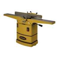
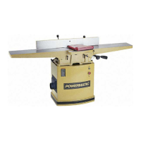
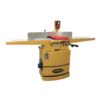
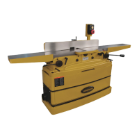
Why does my Powermatic 54HH Power Tool cutterhead slow down during operation?
- JJavier MartinezAug 12, 2025
The cutterhead on your Powermatic Power Tool might slow down while operating if you are feeding the workpiece too quickly or applying too much pressure. Try feeding more slowly or applying less pressure to the workpiece.