7
5.0 Assembly
Tools required for assembly & adjustments:
10mm open-end wrenches (or sockets with
ratchet wrench)
Cross point screwdriver #3
Hex keys, 5mm and 6mm
Combination square
Adjustable square
Rubber mallet (or hammer and wood block)
Straight edge
Additional tools required for optional wood extension
table:
Electric drill
1/4” drill bit
C-clamps, 4” or 6”
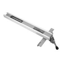
The following instructions are for installing the Accu-
Fence and Rail System on a Powermatic Model 64A,
64B or PM1000 Table Saw. The rails should bolt to
the Powermatic saw without any drilling.
5.1 Front Rail Installation
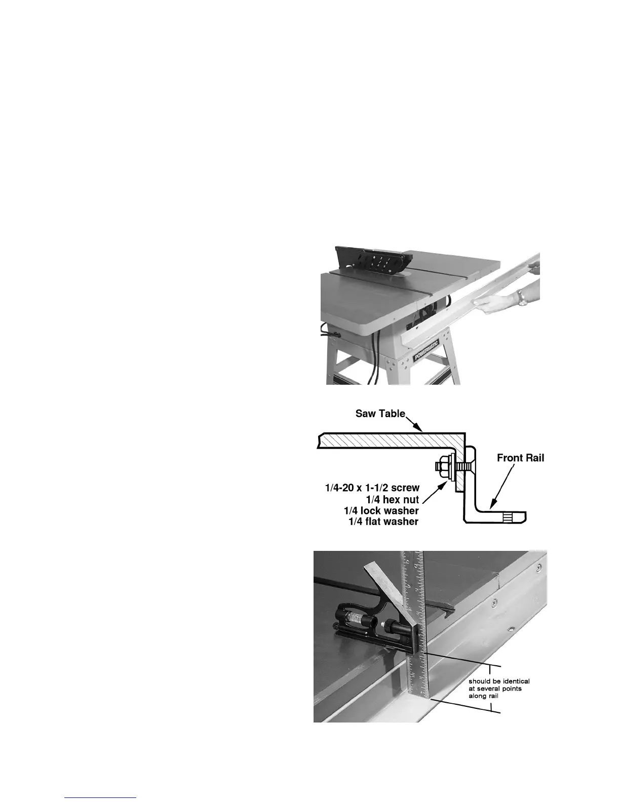
Refer to Figure 3:
1. Identify the front rail, which is 2" x 2" with holes
running along each side.
2. Align the countersunk holes on the front rail to
the four holes in front edge of saw table, as
shown in Figure 3. (The slotted holes will face
down.)
Refer to Figure 4:
3. Lightly secure front rail to saw table and
extension wings, with four 1/4 x 1-1/2 flat head
screws, four flat washers, four lock washers, and
four hex nuts. Tighten just enough to hold rail
next to table but keep loose enough to allow
height adjustment.
The front rail must be parallel to the table top in order
for the Accu-Fence system to function properly.
4. Place an adjustable square on the table as
shown in Figure 5.
5. Check the height of the front rail at several
locations along the surface of the saw table. The
measurements should be the same along the
length of the rail. (Generally, this dimension will
be about 2-1/4”.)
6. When the front rail has been correctly positioned,
tighten all hex nuts securely with a 10mm
wrench.
Figure 3
Figure 4
Figure 5
 Loading...