21
DigiMod 500 1000 1500 2000HV 1000NPS | SERVICE MANUAL
INDEX
10. DSP FW installation procedure:
Once the repairing procedure is over, reset the DSP
board by upgrading the FW.
DigiMod comes with two types of DSP boards:
DSP-C (Black PCB, 4 Micro Match)
DSP-D (Blue PCB, 3 Micro Match)
Select the appropriate preset from the Preset Bank
Selection control dials, by confronting the aforementioned
table.
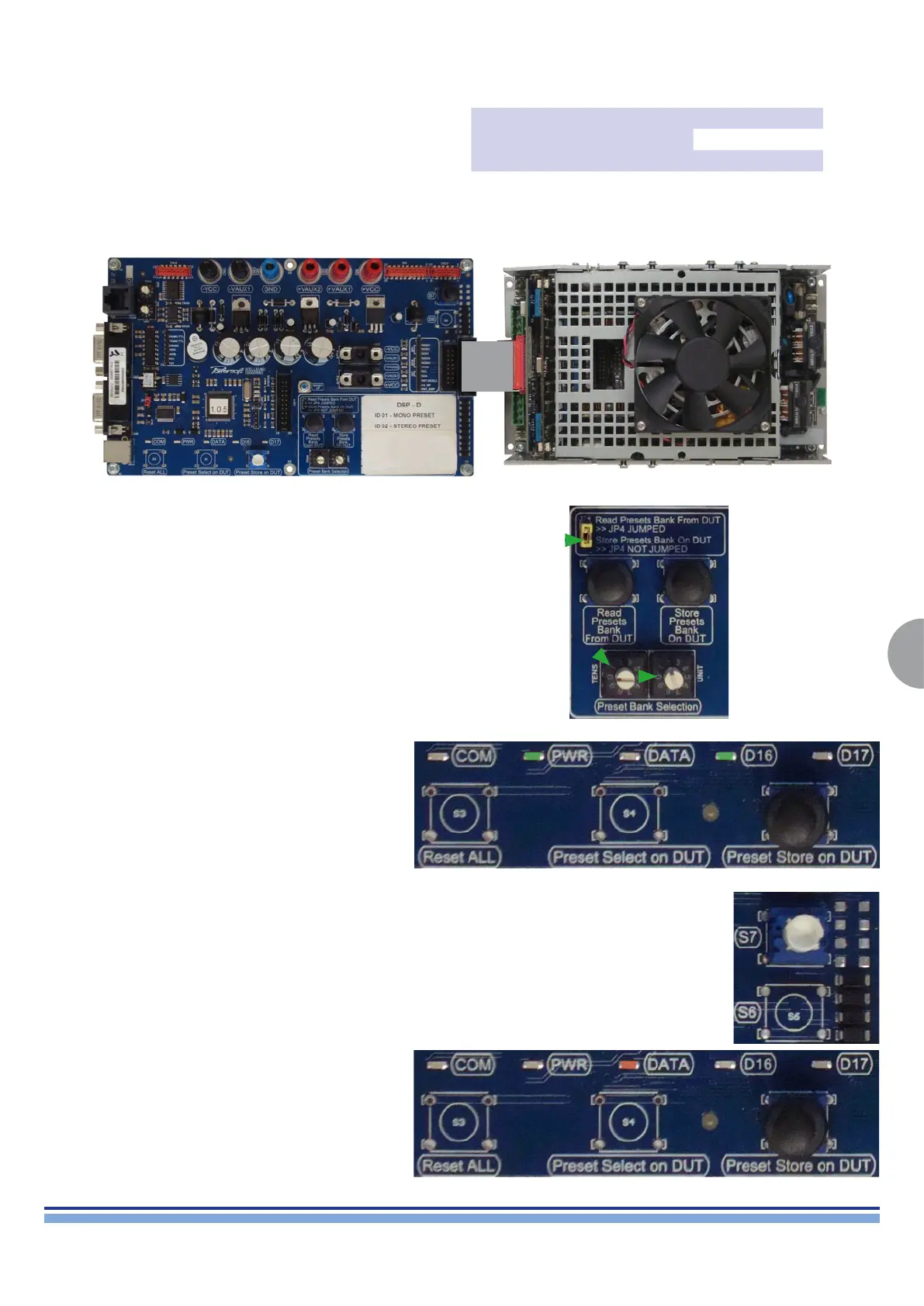
Verify the position of jumper 4 should be “OPEN” (Fig. 20)
Turn on the module and wait 10 sec.
(Fig. 20)
Verify if the green power led “PWR” and “D16” are on (Fig. 21)
(Fig. 21)
Wait for the 3 beeps signaling the end of the FW upgrade
procedure.
Turn off the module and remove the ribbon cable
Press switch “S7” on the programming board
Verify if the orange led “DATA” is blinking (Fig. 22)
(Fig. 22)
DSP Version Firmware Version
Preset
Tens Units
DSP-C 1.2.0 1 0
DSP-D 1.0.0 1 0
After having identied the board, connect the ribbon cable between the respective matching Programming Board and the Module’s DSP
board (Or the interface board if present). (Fig. 19)
(Fig. 19)

 Loading...