Connections | 7
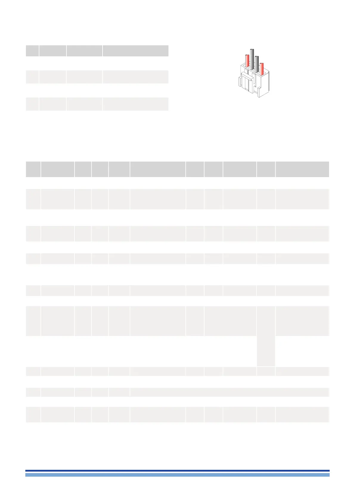
11 : 2.4 . PL1000 pinout
Pin#
Power
polarity
Loudspeaker
polarity
Description
1 GND +
Channle 2 POSITIVE
unbalanced output
2 HOT –
Channle 2 NEGATIVE
unbalanced output
3 GND –
Channle 1 NEGATIVE
unbalanced output
4 HOT +
Channle 1 POSITIVE
unbalanced output
PIN# Name IN OUT POWER Range
Scale
factor
Imped-
ance
Notes
Tole-
rance
Description
19 +VCCMON
LiteMod= +4.25 V
dc
Nominal
LiteMod HV= +6 V
dc
Nominal
20V/V 4.5 kΩ Rail Bus Negative Monitor
20 MUTE
Active Low,
To be pulled to GND by
current sink of at least
20 mA
CH1 and CH2
Output Stage Mute
(disable output stages
PWM)
21 -12VDCOUT
–12 V
DC
; 0.2 A max output
current available
±15%
Negative regulated analog
section supply
(same as pin 14)
22 +12VDCOUT
+12 V
DC
; 0.5 A max output
current available
±15%
Positive regulated analog
section supply
(same as pin 13)
23 TEMPMON12
0 – 5 V
See
table 1
7 kΩ NTC sensor tap output
24 IOUT2MON
8.35
A/V
4.5 kΩ
Channel 2
Output Current Monitor
25 PROTECT2
Level 1
(4 to 5V
dc
) = not in Protection
Level 0
(0 to 1V
dc
) = Protection
330Ω
Channel 2
Output Stage Protection
Monitor
26 VOUT2MON
20 V/V 4.5 kΩ
Channel 2
Output Voltage Monitor
27 GND
Ground
28 IN 2 –
3Vrms for full output
(LiteMod STD)
4.2Vrms for full output
(LiteMod HV)
7Vrms Absolute MAX input
(LiteMod STD and HV
Differential= 3 kΩ
Common Mode= 3.5 kΩ
(BAL)
3.5 kΩ (UNBAL)
Absolute MAX Input: 8V
rms
Channel 2 Balanced Input
(inverting)
Channel 2 Unbalanced
Input (inverting when
shorting pin 29 to ground)
29 IN 2 +
3Vrms for full output
(LiteMod STD)
4.2Vrms for full output
(LiteMod HV)
7Vrms Absolute MAX input
(LiteMod STD and HV)
Differential= 3 kΩ
Common Mode= 0.95 kΩ
(BAL)
1.5 kΩ (UNBAL)
Channel 2 Balanced Input
(non inverting)
Channel 1 Unbalanced
Input (non inverting when
shorting pin 28 to ground)
30 GND
Ground
31 +5VDCOUT
+5 V
DC
; 0.1 A max output
current available
±5%
32 MODEL ID
Amplier Model ID Resistor connected between pin 32 and GND (inf. Ω)
33 RESERVED
34 SDPWS
Active High,
Logic input 3.3 to 12 Vdc
1 kΩ
Logic input to
be fed by “OR”
diode
Power Supply Shut Down
...continued from previous page.
CH1 +
CH1 –
CH2 –
CH2 +
Loudspeaker wires
housing: JST VHR-4N