Do you have a question about the powersoft LiteMod 4HC and is the answer not in the manual?
Explanation of graphical symbols used for warnings and information.
Key safety instructions for operating and maintaining the amplifier module.
US regulatory compliance statement for the device.
European directive concerning waste electrical and electronic equipment.
EU conformity statement and applied harmonized standards.
Guidelines for handling sensitive electronic components to prevent damage.
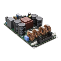
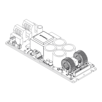
Introduction to the LiteMod 4HC module and its features.
Instructions for inspecting the product upon arrival for damage.
Guidance on environmentally friendly disposal of packaging materials.
Guidance on calculating heatsink thermal resistance and performance.
Using an EMC filter for improved AC mains compatibility.
Guidelines for optimal wiring to minimize RF noise.
How to use ferrite cores to reject RF noise from cabling.
Importance of chassis shielding for reducing RF emissions.
Recommended fuse specification for AC mains overcurrent protection.
Proper grounding procedures for safety and compliance.
Mechanical and electrical grounding requirements for the module.
List of connectors used on the LiteMod module.
Detailed pinout configuration for the PL1 connector.
Detailed pinout configuration for the PL2 connector.
Detailed pinout for PL1000 and PL3000 connectors.
Detailed pinout for PL1001 and PL3001 connectors.
Explanation of the status indicators provided by the LEDs.
Explanation of signal polarity for power supply efficiency.
Various output connection configurations available for the module.
Description of the fan speed control based on temperature.
Overview of protections implemented in the power supply section.
Fuse protection against dangerous mains overcurrents.
Protection mechanism against AC mains overvoltage.
Thermal protection for power supply components.
Limiter for total output current and power.
Overview of protections implemented in the amplifier section.
Protections against damaging input signals.
Protection against amplifier output short circuits.
Protection against short-term and long-term RMS output current.
Protection against high-frequency stationary signals.
Function to smooth out signal clipping with specific attack/release times.
Protection against current mismatch in PTL mode.
Details and bill of materials for the AC mains cable kit.
Details and pinout for the 4x SE output cable.
Details and pinout for the 2x BTL output cable.
Details and pinout for the 2x PTL output cable.
Details and pinout for the 1x PBTL output cable.
Explanation of the various switch functions on the evaluation board.
Identification and description of test points on the evaluation board.
Explanation of the status indicators provided by the LEDs on the board.
Description of the EVB's voltage and thermal limiting features.
How to mute or unmute channels using the EVB switches.
Functionality of the auxiliary voltage selector switch on the EVB.
Description of the EVB's energy saving features and behavior.
Explanation of the LED bar indicating temperature thresholds.
How to bypass specific features or the entire EVB.
System block diagram of the evaluation board.
Identification of components on the PCB via silkscreen labels.
Circuit schematic diagrams for channels 1 and 2.
Circuit schematic diagrams for channels 3 and 4.
Schematic details for power and energy save related circuits.
Information on product service and authorized service centers.
Terms and conditions of the product warranty.
Procedure for returning goods under warranty.
Powersoft's policy on product repair or replacement.
Details on transport costs and responsibilities for warranty service.
Procedure for obtaining technical assistance and support.
| Channels | 4 |
|---|---|
| THD+N | < 0.1% |
| Input Sensitivity | 1.4 Vrms |
| Cooling | Convection |
| Input Type | Analog |
| Input Impedance | 10 kOhm |
| Signal to Noise Ratio | > 110 dB |
| Frequency Response | 20 Hz - 20 kHz |
| Input Connectors | XLR |
| Operating Voltage | 90-264 V AC |
| Type | Amplifier |