Connections | 9
Pin# Name Type Description Range
Scale
Factor
Impedance
28 IN 4- IN
Channel 4 balanced input (inverting)
3VRM S i npu t for fu ll ou tpu t
Absolute MAX input= 8VRMS
\
Differential= 3KΩ
/ Common mode=
3.5KΩ (bal)
Channel 4 unbalanced input (inverting,
when shorting pin 29 to GND)
\ 3,5KΩ (unbal)
29 IN 4+ IN
Channel 4 balanced input (non-inverting) \
Differential= 3KΩ
/ Common mode=
0,95KΩ (bal)
Channel 4 unbalanced input ( non-invert-
ing, when shorting pin 28 to GND)
\ 1,5KΩ (unbal)
30 GND POWER
31 +5VDC OUT POWER
Regulated +5VDC (+/-5%) supply output.
Same as pin 4. Same as pin 4 and 31 on
PL1000
Max current available= 100mA \ \
32 RESERVED \ \ \ \ \
33 READY 4 OUT
Channel 4 PWM state. High when output
1&2 PWM generation is enabled
VOH= 5VDC / VOL= 1VDC \ 100KΩ
34 SDPWS IN
Power supply shut down. Active High.
Enable enegy save mode (consumption
<1W). Same as pin 1. Same as pin 1 and 34
on PL1000
3,3VDC< VIH <12VDC \ 4,7KΩ
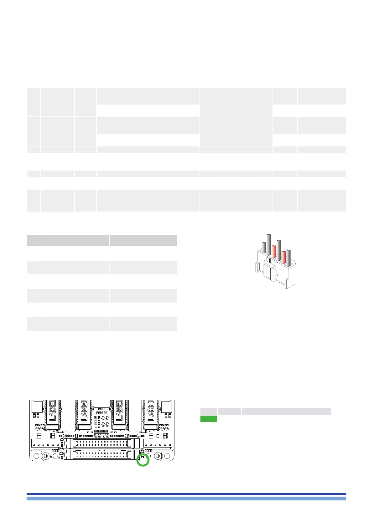
11 : 3.LED encoding
A single LED is located on the point indicated in the picture.
11 : 2.4 . PL1001, PL3001 pinout
Pin# PL1001 Polarity PL3001 Polarity
1 CH1 (-) CH2 (+)
2 CH1 (+) CH2(-)
3 CH3 (-) CH4 (+)
4 CH3 (+) CH 4 (-)
5 GND GND
6 PARALLEL PARALLEL
1
6
Color Status Description
solid off OFF - amp is off
solid on READY - amp is ready to be used
Loudspeaker wires
housing: JST VHR-6N