8
Thermal constraints
This device must be correctly heatsinked for proper and
reliable operation: an appropriate external passive heat sink
guarantees by design thermal efciency and reliability.
Proper heatsink planarity is strongly suggested to al-
low thermal transfer from the module’s bottom plate to the
heatsink; a thermal compound may be used, but it is not
strictly necessary.
In order to ensure proper ventilation of the module, rea-
sonable spacing of at least 100 mm must be left between
the frame of the unit and any side component or surface of
the enclosure.
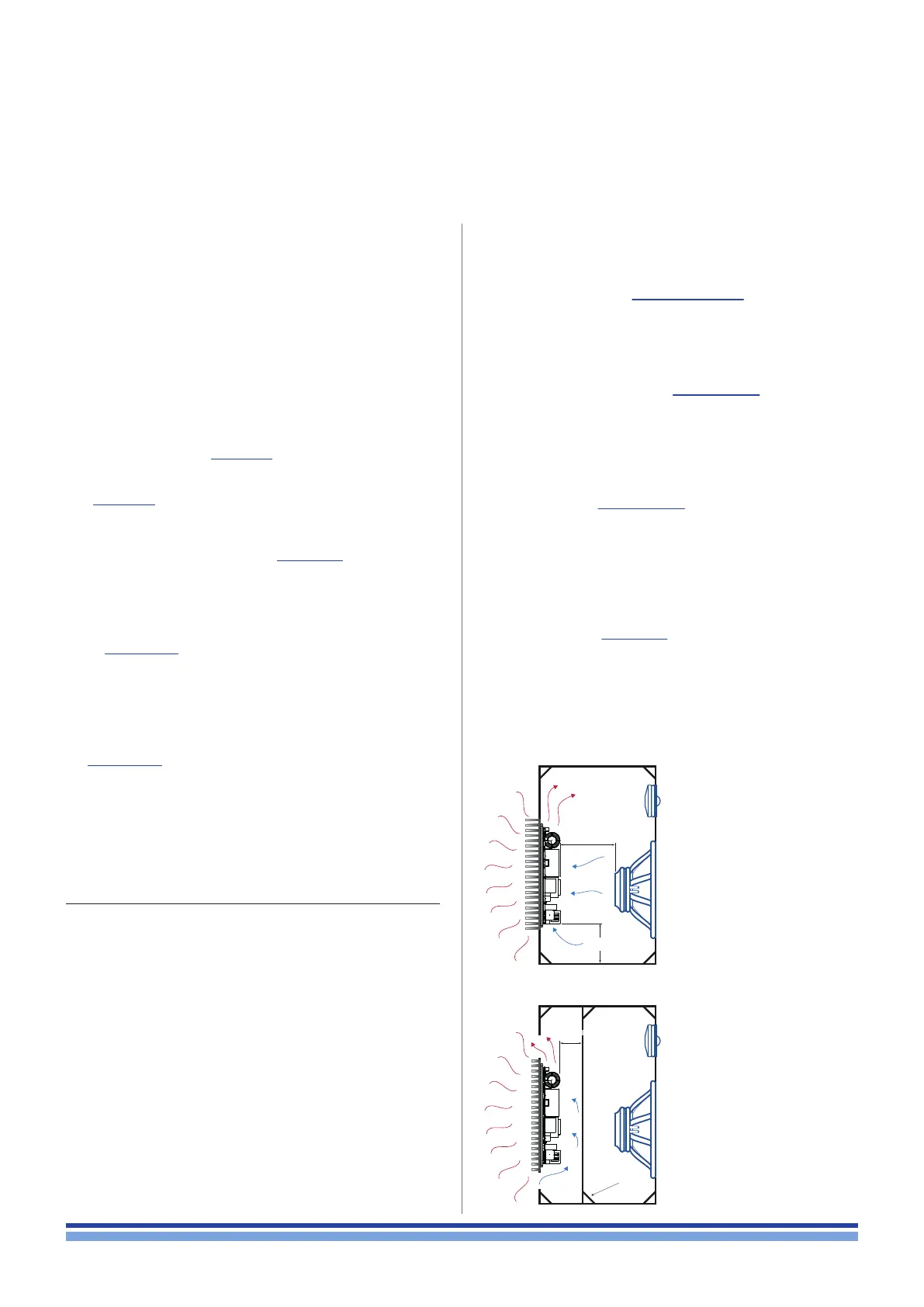
The module has been designed to t into a loudspeaker
cabinet: please refer to FIGURE 1 for proper module placing.
IN FIGURE 1 HEATSINK FINS ARE SET HORIZONTALLY
(WRONG!) ONLY FOR DESCRIPTIVE PURPOSE.
All conguration showed in FIGURE 1 are viable for
proper module placing and cooling. We suggest to posi-
tion the module vertically with respect the ground in order
to take advantage of the chimney effect for ventilation and
heat dissipation.
In FIGURE 1.a the module and the loudspeakers share
the same room into the cabinet. This is the default place-
ment solution: it allows good ventilation because of woofer
diaphragm movement and high air volume; be aware of
magnetic eld interaction: place the module far enough from
loudspeakers magnet in order to prevent fans blockage.
FIGURE 1.b shows the more efcient cooling congura-
tion, even if it is less effective against dust and moisture
that can get into the module. By allowing external air ow,
it is possible to reduce the ns width on the heatsink by
maintaining good cooling performances.
8 : 1.Heatsink performance
Here we suggest a rule of thumb to calculate the thermal
resistance of the heatsink.
The absolute thermal resistance of the heatsink is the
temperature difference (kelvin or celsius) across it structure
when a unit of heat energy ows through it in unit time (watt).
For seek of simplicity: a heatsink with low thermal resistance
offers high heat dissipation, as well as a low electric resist-
ance allows high current owing through a conductive wire.
In order to dene the maximum allowed thermal resist-
ance for the heatsink let assume the following:
e as the amp module efciency
cf as the crest factor of the audio signal
W
max
as the peak power delivered by the module
T
amb
as the highest ambient temperature
T
mod
as the highest operating temperature
The thermal resistance of the heatsink derives from the fol-
lowing formula:
The maximum dissipated power can be calculated as:
set at 75°C (167°F) on the bottom plate and stating an ambi-
ent temperature of 45 °C (113°F), the previous example gives:
meaning that the temperature of the bottom plate is always
lower than 75°C if the heatsink has a thermal resistance
better than 0.14°C/W (or 0.14 K/W) with ambient temperature
up to 45 °C.
For example, stating an efciency of 80%, 6 dB crest factor
and 3400 W peak power, the dissipated heat is:
Supposing that the thermal protection of the module (T
mod
) is
100 mm
3.94 inch
Be aware of
magnetic leakage
MIN.
Do not obstruct
air ow
Be aware of
air leakage
FIGURE 1: Cooling solutions
(for descriptive purpose
the heatsink fins are set in
wrong direction);
a) Module and loudspeaker
into the same chamber;
b) Module in a separate
vented chamber.
Dissipated power =
cf
W
max
(1 - e)
R
th
=
Dissipated power
T
mod
- T
amb
= 0.14°C/W
170
75 - 45
= 170 W
4
3400 (1 - 0.8)
2 | LiteMod 4HC | User guide
a
b