8 | LiteMod and LiteMod HV | User guide
11 : 3.Internal Signal Path Polarity
In order to increase the power’s supply energy storage
efciency, signals coming from channel pairs 1-2 are polar-
ity reversed, one with respect to the other within the pair,
when entering the amplier. This ensures a symmetrical use
of the voltage rails: if, for example, both channels’ 1 and 2
input signals are going through a peak at the same time,
channel 1’s energy will come from the positive voltage rails
while channel 2, whose polarity is reversed with respect to
channel 1, will be fed energy from the negative voltage rails.
In this manner, the power supply will work symmetrically,
with one channel catered by the positive rails and the other
by the symmetrical negative rails. Channel 2’s signal will be
polarity reversed once more to ensure that both channels
output with the same polarity as their corresponding input
signals.
For this reason it is very important not to invert the po-
larity of either channels before feeding them to the module.
A double polarity inversion (the rst by the user inserting
the input signal and the other by the amplier’s internal
circuitry) results in no inversion at all. If this were the case,
both channels would be weighing on only one side (positive
or negative) of the power supply’s voltage rails. This would
result in an inefcient use of the power supply’s energy.
Please pay special attention in using balanced inputs on
all measurement equipment (such as oscilloscope probes)
when you are bench testing.
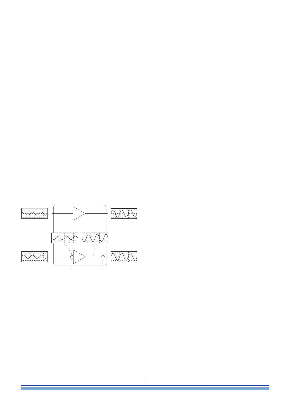
rst polarity
inversion
second polarity
inversion
Channel 1
input
Channel 2
input
Channel 1
output
Amp
Channel 2
output
FIGURE 8: Internal signal path polar-
ity with example input signals. Both channels
1 and 2 are fed with the same sine signal.