INDEX
10
M SERIES | SERVICE MANUAL
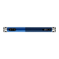
This done, it is now time to remove the 4 outmost hex
screws lacated on the heatsink and highlighted in (Fig.
15)
It is now possible to remove the board from the amplier’s chassis. Lift the board from the connector’s side and gently pull it paying
attention not to damage any of the components.
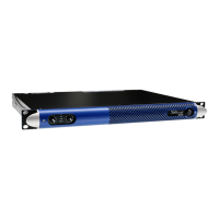
6. Removing the fan:
Before removing the fan, make sure the power supply
capacitors have been discharged as explained in chapter
3.
To remove the fan, begin by unscrewing the fans power
cables highlighted in (Fig. 16)
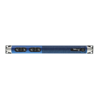
Now the fan can be unscrewed from the amplier chassis
by removing the three screws highlighted in (Fig. 17)
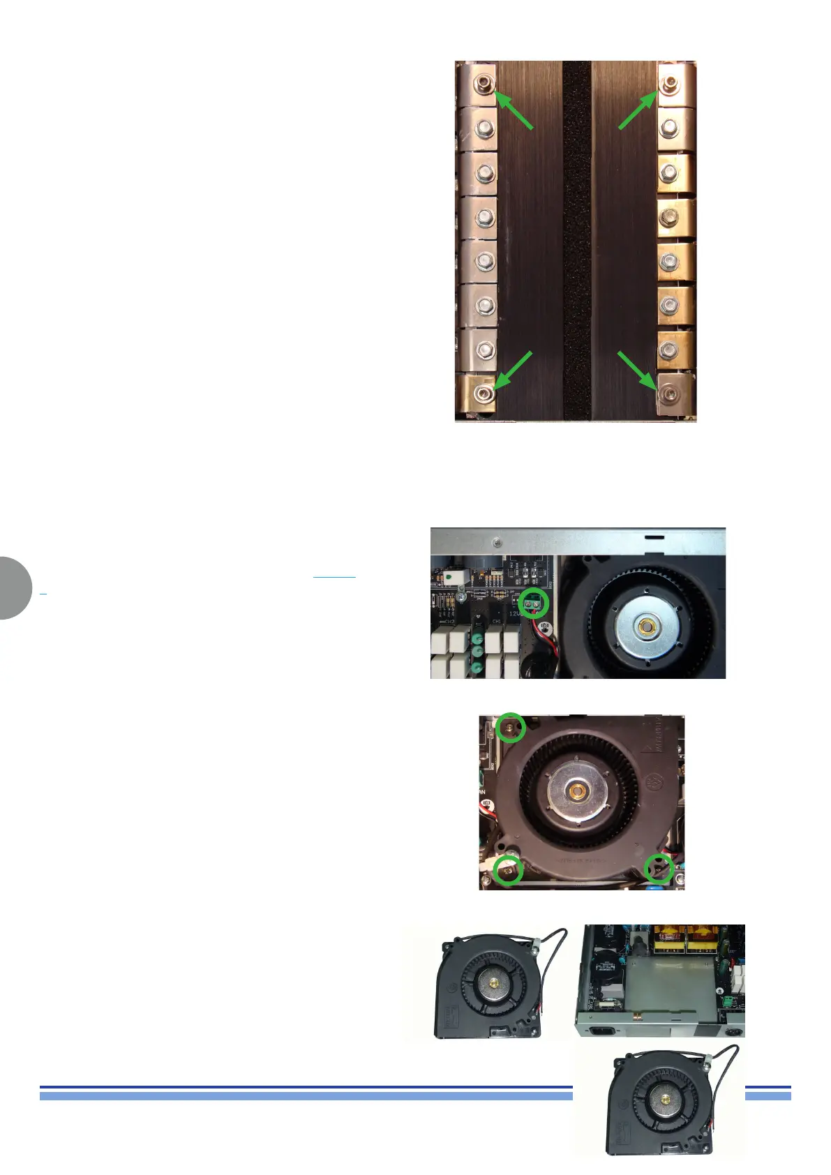
(Fig. 18) portrays the fan removed from the main chassis
and the chassis itself.
(Fig. 15)
(Fig. 16)
(Fig. 17)
(Fig. 18)