4 | T Series
EN
Locaon
Install your amplier in locaon that allows some exchange of air.
Amplier comes with mounng accessories for the following
mounng opons
Surface mount – Using 2 “bracket B” it’s possible to mount an
amplier vercally on a wall or upside down under a table or in a
ceiling.
Tandem 19” rack mount – Using the 2 “bracket B” it’s possible to
mount two Mezzo side to side and then mount them using the 2
“bracket A” in 1 RU in a 19” rack.
Single 19” rack mount – Using the 2 “bracket A” it’s possible to
mount a single amplier in a 19” rack.
Single half rack mount – Using the 2 “bracket A” it’s possible to
mount a single amplier in a half width rack.
On a shelf – Aach the rubber feet to the boom of the amplier
and place it on the desired surface.
Plenum mount – 320 W models are approved for placement in air
handling spaces above the ceiling if the mains cable is mounted
inside the plenum mount accessory (sold separately).
Custom mount – It’s possible to custom design ngs for poles and
other applicaons using screws ng the threaded holes in the
amplier. These screws must not be longer than XX mm. The safest
way to avoid mistakes is to use the provided screws.
Cooling
The 600W models implement a temperature controlled forced-air
cooling system. Air enters from the front and exists at the back of
the amplier. The fan has 3 modes:
STILL - if the temperature of the space surrounding the amplier is
≤35C and the average power out is ≤1 W per channel. (≤84 dB SPL*)
WHISPER - if the average output is ≤4 W per channel. The fan noise
at 1 m is ≤30 dBA in this mode. (≤90 dB SPL*)
REGULATED - Mezzo adapts the speed of the fan to stay cool. The
fan noise at 1 m is ≤45 dBA in this mode. (≤105 dB SPL* depending
on model and power sharing)
In the rare event of overheang the amplier will mute all channels
and run the fans to reach a safe temperature and start operang
again.
It’s ok to stack ampliers on top of each other in a rack, but it’s
recommended to put them in banks of 4 RU and then leave a 1 RU
space.
*(SPL at 2 m with 90 dB1W1m sensivity)
Package list
The box contains the following:
1 Mezzo amplier
Block connectors
4 rubber feet
2 Bracket A
2 Bracket B
6 screws (for aaching the brackets)
Mains power cable
Preliminary operaons
The amplier comprises a comprehensive range of funcons that
can be setup in two ways.
• Automac - without the use of any app or soware.
• Advanced - use the soware to set more parameters and
opmize the funconality.
DSP and matrix conguraon
This amplier does not have a power switch. It will turn on
automacally when AC power is connected and it will go to standby
mode if no signal is present for 25 minutes.
When input signal exceeding -60 dB relave the level needed for
full power is applied the amplier will go back on within 2 seconds.
70V
LED
100V
LED
Max Peak
Voltage
Max RMS
Voltage
Descripon
Unlit Lit 141.4 V
peak
100 V
rms
Also works in mixed 100V and low
impedance conguraons
Lit Unlit 100 V
peak
70.7 V
rms
Also works in mixed 70V and low
impedance conguraons
Lit Lit 35.4 V
peak
25 V
rms
Also works in mixed 70V and low
impedance conguraons
Unlit Unlit Custom Sengs
This can’t be selected on the rear panel.
The limiters have been set manually
in the soware and can’t be changed
without a reset to factory defaults
This is a very easy way to congure the amplier that doesn’t
require any soware. It is ideal if all you want is an amplier with a
at frequency response that can monitored and if it is an AD model
get audio routed to it with third party soware.
The automac setup will set limiters so that a channel reaches the
maximum capacity of the power supply with -4 dBu balanced analog
input (or -6 dBFS for Dante/AES67). This means that it also adjusts
the gain so that the amplier has the gain needed for all channels.
The way to “assign power” is then simply done by adjusng the
level of the content to the dierent channels.
It will also set the high pass lters automacally. The cuto will be
selected so that frequencies below the resonance frequency as well
as frequencies that saturate transformers in Hi-Z loudspeakers will
be aenuated.
Note! Automac conguraon is only possible when the amplier is in its
factory default mode. Factory default is indicated by 5 seconds long blinks
of the 70V and 100V LEDs. In order to restore Mezzo's factory default
mode, press and hold the mode buon on the rear panel for 10 s.
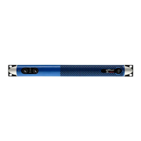
Step 1 – Calibrate
STATUS
NETWORK
SIGNAL
SWITCHED
70V
100V
25V
CAL
6s
3s
CTRL +CTRL +
CTRL
I4 I3 I2 I1 5V
-10 dBV
4 IN 3
MAINS
2 1
2 IN 1
OUT4 3
MEZZO 602 AD
STATUS
NETWORK
SIGNAL
70V
100V
25V
CAL
6s
3s
I4 I3 I2 I1 5V
-10 dBV
4 IN 3
MAINS
2 1
2 IN 1
ETH
OUT4 3
RESET
MEZZO 322 A
STATUS
NETWORK
SIGNAL
70V
100V
25V
CAL
6s
3s
I4 I3 I2 I1 5V
IN2 1
-10 dBV
4 IN 3
MAINS
4 3 2 1
2 IN 1
RESET
ETH
MEZZO 324 A
STATUS
NETWORK
SIGNAL
SWITCHED
70V
100V
25V
CAL
6s
3s
CTRL +CTRL +
CTRL
I4 I3 I2 I1 5V
IN2 1
-10 dBV
4 IN 3
2 IN 1
Press the mode buon unl it fast blinks twice aer 2 s, release it
within 2 s aer it has blinked. This will trigger an automac impedance
measurement taking 1 s per channel. This will be made at a level that is
high enough to properly measure an 8 ohm loudspeaker. If the impedance
is higher the measurement might be deemed to be too noisy and it will
then repeat itself automacally. Please note that it may generate an SPL
exceeding 95 dB if the loudspeakers are sensive enough.
The impedance measurement will automacally set warning thresholds
monitoring change. It will also set the limiters so that the channel can
play as loud as the design and model allows, without distoron.
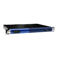
Step 2 - Select the maximum voltage
STATUS
NETWORK
SIGNAL
SWITCHED
70V
100V
25V
CAL
6s
3s
CTRL +CTRL +
CTRL
I4 I3 I2 I1 5V
-10 dBV
4 IN 3
MAINS
2 1
2 IN 1
OUT4 3
MEZZO 602 AD
STATUS
NETWORK
SIGNAL
70V
100V
25V
CAL
6s
3s
I4 I3 I2 I1 5V
-10 dBV
4 IN 3
MAINS
2 1
2 IN 1
ETH
OUT4 3
RESET
MEZZO 322 A
STATUS
NETWORK
SIGNAL
70V
100V
25V
CAL
6s
3s
I4 I3 I2 I1 5V
IN2 1
-10 dBV
4 IN 3
MAINS
4 3 2 1
2 IN 1
RESET
ETH
MEZZO 324 A
STATUS
NETWORK
SIGNAL
SWITCHED
70V
100V
25V
CAL
6s
3s
CTRL +CTRL +
CTRL
I4 I3 I2 I1 5V
IN2 1
-10 dBV
4 IN 3
2 IN 1
No channel will ever be assigned limiters that exceed the power
of the power supply. The main reason for selecng the maximum
voltage is to ensure that 25/70/100V loudspeakers will get the
power selected on their tapping if a channel is using less power
than it can deliver.
If the applicaon is 25V or 70V, then there is a risk that the limiters
get set too high if the connected load isn’t requiring full power. This
is xed with short presses on the mode buon unl it shows the
desired maximum voltage:
 Loading...