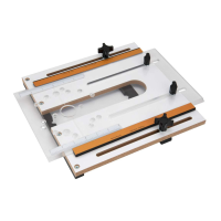
FENCE ASSEMBLY
8
8
FENCE ASSEMBLY
Figure 11 BACK
Refer to Figure 11–13
• Remove the adhesive backing from the right to left tape
measure and press into place. Start on the right end and
carefully place the tape along the front edge of the fence.
Use scissors to cut the excess tape from the leftend.
• Attach the dust port to the back of the fence using the pan
head screws and 1/4"washers.
• From the front of the MDF adjustable fence faces, insert the
1/4"-20 x 1-1/2" screws through the MDF adjustable fence
face and fence, secure in place with the locking knobs. The
MDF adjustable fence faces can be adjusted left or right, after
adjustment has been made for the operation to be performed,
tighten all knobssecurely.
• From the bottom of the fence insert the two 5/16"-18 x 1-1/2"
T-Bolts through the fence slot. Place a 5/16" washer and
fence locking knob on each T-Bolt. Place the fence onto the
router table and align the T-Bolts in the fence with the slots in
the router table. Tighten the knobs after adjusting the fence to
the operation beingpreformed.
• From the back of the bit guard insert two 1/4"-20x 1" T-Bolts,
place 1/4" washers and locking knobs onto each T-Bolt. Place
the T-Bolts into the T-Slot on the face of the fence and slide
the bit guard onto the fence. NOTE: To adjust the bit guard,
loosen the knobs, slide the bit guard up and down to desired
application and tighten knobs. When changing bits, slide the
bit guard left or right of theopening.
WARNING
To prevent kickback make sure the featherboard is at least
1" (2.5 cm) from the cutter.
• Place a spacer on each 5/16"-18 x 1-1/2" long T-Bolt and insert
through the slot in the featherboard, thread a locking knob on
each T-Bolt and slide the T-Bolts into the T-slot in the front of
the fence. Position the featherboard and tighten lockingknobs.
• Slide the T-Bolt on the ip stop into the T-Slot in top of the
fence, tighten the knob. The arm on the ip stop functions
as an easily adjustable stop and can be ipped up when not
needed. NOTE: The ip stop is multi-functional, please see
ip stop instructions for details. To prevent chip build up, the
stop does not extend the full width of the fence. However
when using a stop with material 3/8" thick or less, a longer
stop will need to be fabricated and can be mounted in the
T-slot located in the front of thefence.
IMPORTANT: Every routing operation is different, adjust the
various parts of the router fence and accessories as needed and
then tighten all knobssecurely.
To Convert from Inboard to Outboard Position
Remove the knob and T-bolt and rotate the stop body 180°.
Replace the knob and T-bolt. See below