TABLE ASSEMBLY
5
TABLE ASSEMBLY
5
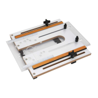
ASSEMBLE BENCH TOP ROUTER TABLE
Model No. 71402
Top (with wood top) A 23-5/8" x 15-3/4" (600x400mm)
Leg Spacing
B 27-1/8" x 19-1/4" (689x489mm)
Height (with wood top) C 15-1/2" (394mm)
Shelf 23-5/8" x 15-3/4" (600x400mm)
Shelf Height 14-1/2" (369mm)
WARNING
Refer to Figure 3–10
Do not use the bench top router table until it is completely
assembled and you have read and understood this entire
operating manual and the operating manual of the tool being
used with this bench top routertable.
Figure 3
1. Attach short tie bar(CC) to each pair of legs (AA) using
carriage bolts 5/16"-18 x 3/4" (DD), lock washers 5/16" (FF)
and nuts 5/16"-18 (EE). Finger tighten thenuts.
Figure 4
2. Attach short rail/leg assembly to each long rail (BB) using
four carriage bolts 5/16"-18 x 3/4" (DD), lock washers 5/16"
(FF) and nuts 5/16"-18(EE). Finger tighten thenuts.
Figure 5
3. Hand tighten Adjustment screw (JJ) into the hexagon set
screw (HH). Place the assembly into the holes in the insert
opening and tighten hex nut (I I) against the bottom of the
table. Place hex nut (KK) onto adjustment screw (JJ). DO
NOT tighten at this time. Repeat for all four holes.
Figure 6
4. Place leg assembly upside down (Figure 6) then position onto
bottom of assembled table top. Align holes in top of each
leg with pre-drilled pilot holes in the table. Fasten the Leg
assembly to the top with eight 3/16" coarse-thread screws
(QQ) Use handheld screw driver to prevent stripping screws.
Do not overtighten.
5. Turn the assembly right-side up and tighten all sixteen nuts
(EE) on leg/rail assembly.