6
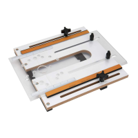
TABLE ASSEMBLY
Router Drill Patterns
Figure 7
1. Insert plate (MM) has lettered center points molded into
the bottom face using drill patterns for the most common
routers. Locate your router on the following chart and use
the lettered pattern indicated. Drill a hole matching the size
of the mounting screws supplied with your router. Once the
holes are drilled, ip the insert plate over and counter bore,
or counter sink the drilled holes to seat the mounting screws
below the surface of the mounting plate.
NOTE: Drill holes and counterbores or countersinks to
accommodate the mounting screws supplied with the router. For
routers equipped with a built-in lift system, use the router sub-
base as a guide for the location and size of the access hole and
as a drillingguide.
PORTER
CABLE*
A 690 Series A 8529
A 7529
DEWALT*
F DW621 A DW616 Series
F DW625 A DW618 Series
Craftsman*
C 315 275 000 E 315 175 060
D 315 175 040 D 315 175 070
D 315 175 050
Bosch*
A 1617 (fixed base) A 1618
G 1617 (plunge base) A MR23 Series
Makita* A RF1101
Ryobi* C R1631K
Milwaukee*
A 5615 A 5616
A 5619
Fein* F FT 1800
Elu* F 177
Hitachi* A M-12VC
* PORTER-CABLE, DEWALT, Craftsman and Elu are trademarks of The Stanley
Black & Decker Corporation—Bosch is a trademark of the Robert Bosch Tool
Corporation—Makita is a trademark of Makita Corporation—Ryobi is a trademark
of Ryobi Limited and is used by Techtronic Industries Company LTD—Milwaukee
is a trademark of Techtronic Industries Company LTD—Fein is manufactured by C.
& E. Fein GmbH—Hitachi is a trademark of Hitachi, Ltd.
For routers not covered by the Chart follow the
instructions below
With target pattern facing up—place insert plate (MM) onto
workbench. (Figure 8)
a. Remove sub-base from router. Check router base holes to
ensure alignment with any of the center point patterns. If so,
use that pattern.
b. If no existing patterns match up, select a drill bit that ts the
mounting holes of your subbase. If router is equipped with a
built-in lift system, select a bit that ts the lift-access hole.
c. Apply several small pieces of double-faced tape to the insert
plate. Now, center the sub-base on the plate, using the
concentric arcs of the target pattern as guides.
d. Keep in mind preference of router control position. Check
that holes to be drilled align with the threaded hole for the
start pin or the predrilled center points. Press the subbase
rmly onto the insert plate.
NOTE: Before drilling, securely clamp the insert plate to
drill-press table or bench to prevent movement while drilling.
Whether using a drill press or hand drill, place a wood scrap
under the insert plate to reduce chipping as the drill bit passes
through the plate. Performing this operation on a drill press
ensures the holes will be perpendicular to the plate.
e. Use the holes in the sub-base as a pattern and mark the
needed holes, drill the holes in the insert plate with a drill
press or hand drill.
Figure 8
Figure 9
f. With holes drilled, remove sub-base from insert plate. Flip
plate over and countersink mounting holes assuring machine
screw heads sit below plate surface when tightened.
 Loading...