Do you have a question about the PowerTech MP-3739 and is the answer not in the manual?
Highlights specific dangers like fire, explosion, and battery acid hazards.
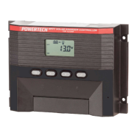
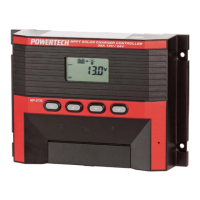
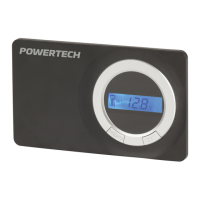
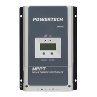
Identifies and describes the controller's display screen and front panel buttons.
Shows battery voltage, capacity, and system operation overview.
Allows manual switching of the connected load ON or OFF.
Displays the current flowing into the battery from the solar array.
Displays the current being drawn by the connected loads.
Sets the ON time for the load after entering night mode.
Sets the OFF time for the load after Timer1 has finished.
Explains automatic charging procedures based on battery level.
Details how the controller prevents battery damage from low voltage.
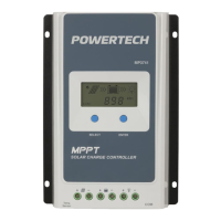
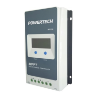
Highlights the use of MPPT technology for maximum solar output.
Describes the availability of a 5Vdc/500mA power supply.
Explains the timer functions for automatic load control.
Details the steps for physically mounting the controller to a wall.
First stage of charging, receiving majority of charge up to 85-95% capacity.
Constant voltage stage allowing battery to absorb current.
Stage after full charge, maintaining battery with minimal current.
Lists faults that do not damage the controller and allow normal operation after correction.
Indicates battery terminals are connected incorrectly.
Signals an issue with battery voltage, possibly requiring recharge or replacement.
Indicates excessive current from the solar module.
Signifies excessive current drawn by the connected loads.
| Brand | PowerTech |
|---|---|
| Model | MP-3739 |
| Category | Controller |
| Language | English |