4
2. Product Appearance Diagram
Product Appearance Diagram
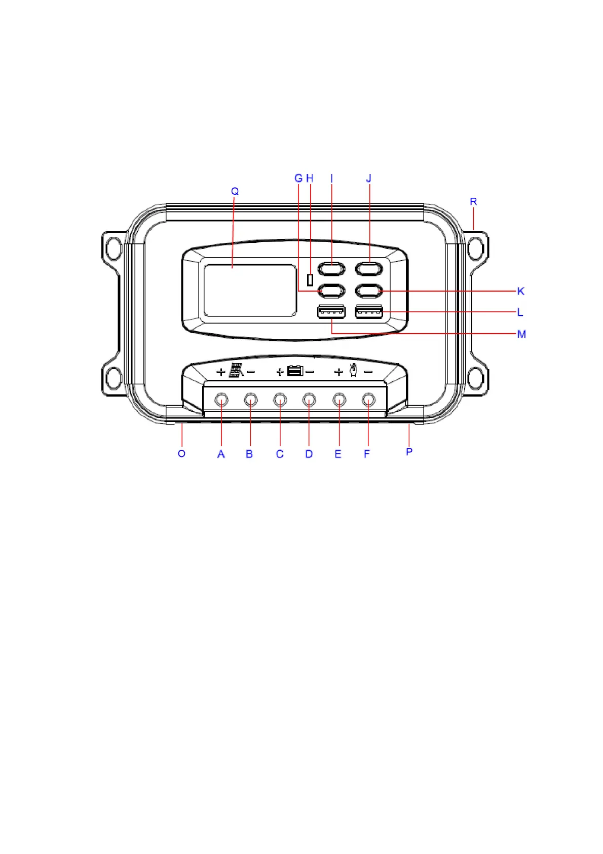
Fig. 1: Structure Diagram
A: Solar input connected to the posive electrode, B: Solar input connected to the negave
electrode
C: Baery connected to posive electrode, D: Baery connected to negave electrode
E: Load output posive, F: Load output negave; E. MODE buon
H: LED indicator light, red light on in case of err
or, flashing green during charging, stay green aer
fully charged.
M, L: USB output interface
J: Menu buon, K: OK buon, I: UP buon, G: DOWN buon
O: External temperature sensing line interface
P: RJ45 han
dle interface (the handle is an LCD, and the display content is the same as the hos
t
LCD)
Q: LCD
R: Screw fixing posion