INSTRUCTIONS PW150/PW200
10
Figure 23 Figure 24
Figure 25 Figure 26
Figure 27
Figure 28 Figure 29 Figure 30
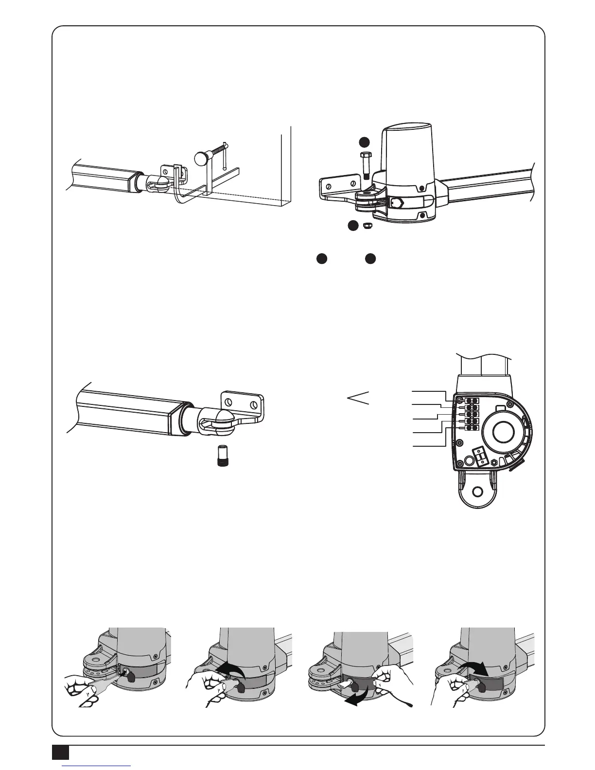
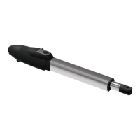
10). Clamp and fix the motor front plate on the door temporarily.
11). Lift up the motor and insert the screws into the front plate.
12). Lift the motor overhead and push the gate to the end until the screw holes of the motor end matches the holes
on the rear plate. Fasten the motor to the rear plate with the bolt as shown in Figure24.
13). Fasten the nut tightly and loosen it for half round for motor supporting in rotating.
14). Fasten the motor front end to the front plate with the bolt and nut tightly. Fully tighten the screw.
15). Use appropriate release key to release the gear motor.
16). Try to push the released gate and make sure the motor can be manually moved easily.
17). Make sure the motor front plate can be fastened on the gate to be installed permanently.
18). Use the appropriate release key to fasten the gear motor again.
19). Loosen the plastic nut under the power cable of the motor end, and penetrate the power cable through the nut
and screw it up.
20). Connect the motor power cable as shown in Figure 26.
A
A
B
B
21). Gear Motor Release (for left motor)
1). Insert the release key to the release slot Figure27.
2). Turn the release key anti-clockwise Figure28.
3). Pull out the release bar Figure29.
4). Turn the release key clockwise to fix the release bar, the release bar has to be in pulled out position
when you turn the release key clockwise Figure30.
5). The turning direction will be reversed for right motor.
White(+)
Yellow(-)
Red(5V)
Green(Signal)
Black(GND)
Motor
Hall Sensor
Hall Sensor
Hall Sensor