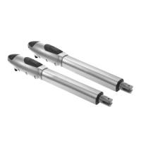
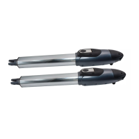
INSTRUCTIONS PW150/PW200
14
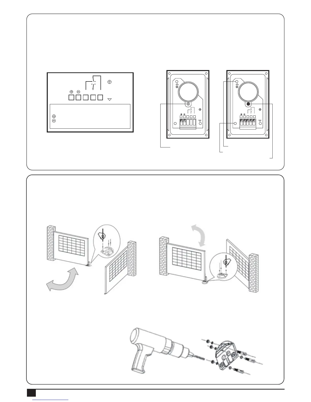
3.3.7 PEL-1 Electric Latch and PS-1 Stopper
1. Stopper:
1). Before installing the stopper, please make sure the gates are in close positions and the surface to be installed is flat.
2). Place the stopper on the ground using the bottom as reference, and mark the 3 drilling points.
See Figure 3.3.7 (1) For the gate opened inward.
See Figure 3.3.7 (2) For the gate opened outward.
Note: If the gate is opened outward, place the stopper in opposite direction.
3). Drill the 3 marked points, and then securely attach the stopper to the ground with screws and washers.
See Figure 3.3.7 (3)
3). Wiring connection:
TX: Connect the (1) and (2) terminals on the transmitter with the terminals GND and 24V on the PL600/ 1000 PCB.
RX: Connect the (1), (2) and NC terminals on the receiver with the terminals GND、24V and PH1 on the
PCB600/1000 PCB. See Figure 3.3.6 (4) Figure 3.3.6 (5).
Figure 3.3.6 (4) Figure 3.3.6 (5)
CA
CC
NA: Normal Open
NC: Normal Close
: DC(+) Input Voltage
: DC(-) Input Voltage
C: Common
CA: AC(12~24)
CC: DC(12~24)
VERT:Vertical
ORIZ:Horizontal
O
R
I
Z
NA NC C
1 2 3 4 5
Power LED: Green
Transmitter
Vertical Adjustment
Horizontal Adjustment
LED:Red(Beam Alignment)
CA
CC
NA NC C
1 2 3 4 5
O
R
I
Z
V
E
R
T
Receiver
CA
CC
NA NC C
1 2 3 4 5
O
R
I
Z
V
E
R
T