POWERWINCH MOTORIZED FOLDING CAMPER WINCH
3
WINCH INSTALLATION
1. Park the camper on a hard level surface. Place wheel chocks under the
wheels to prevent the camper from moving.
2. Make sure that camper top is lowered completely and there is no tension on the
winch cable. Remove the cable from the existing winch.
3. Remove the existing winch. S
AVE the fasteners to install the new winch.
NOTE: If there is not an
existing winch, the installer
must furnish three (3) each
of 3/8-16 x 1 carriage bolts,
lock washers and nuts.
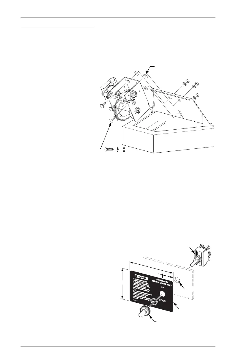
4. Using the fasteners from
step 3 and attach the new
electric winch to the trailer
frame. The included fender
washers go between the
winch and the trailer's
mounting frame. Ensure
that the winch is centered
and vertical. Torque nuts to
20 ft-lbs.
ELECTRICAL SETUP
If mounting the switch in the optional cover, refer to the mounting instructions
included with the cover kit. For reference, refer to the wiring diagram on page 8.
1. Determine the mounting location of the switch. The position should provide easy
access but not in a position where the switch can be accidentally damaged.
For reference:
The cable is 24" from the winch to the switch.
There is 36" of cable from the switch to the battery connection.
Before continuing, lay the cable out to be sure that the switch will mount without
straining the wire cable allowing a minimum of 1"-2" of slack. The cable must
be mounted to avoid moving parts such as the gear train and cable.
2. In the mounting location, drill a
15/32" hole.
3. Clean and dry the surface then
peel off the paper backing from
the switch plate and adhere the
switch plate over the hole. The
hole in the plate must align with
the hole drilled in step 2.
4. Mount the switch using the
supplied jamb nuts and the
rubber switch boot. Orient the
switch so that the notch in the
switch aligns with the tab in the
hole of the switch plate.
5. Route the battery wires to the battery.
Trailer Frame (ref)
Winch
3/8-16 Carriage Bolt,
Lock Washer & Nut
(not included w/ winch)
pwFCW001
3/8 Fender Washer
(Qty: 3)
Switch
Switch Plate
Switch Boot
15/32” Hole
3 3/4”
15/16”
2 5/8”
pwFCW003
 Loading...