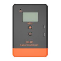
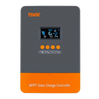
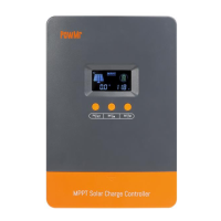
This document describes the Keeper Series MPPT (Maximum Power Point Tracking) Solar Charge Controller, available in 20A, 30A, and 40A models. It is designed to optimize energy harvesting from solar panels and improve the efficiency of solar power systems.
Function Description
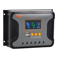
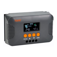
The Keeper Series solar charge controller utilizes an advanced MPPT control algorithm to quickly track the maximum power point of the PV array in various environmental conditions. This ensures maximum energy extraction from solar panels, significantly enhancing the energy utilization in solar systems. The device features a dual display function, including an LCD and an optional remote header, along with a standard communication interface for user extension applications and diverse monitoring needs. It is suitable for applications such as communication base stations, home power supply systems, traffic lights, solar street lamps, and courtyard lamp systems.
Key functions include:
- Maximum Power Point Tracking (MPPT): Advanced MPPT technology with a tracking efficiency of no less than 99.5%.
- High Conversion Efficiency: Utilizes high-quality components to achieve a maximum conversion efficiency of 97%.
- Fast Tracking Speed: Super-fast maximum power tracking speed while maintaining tracking efficiency.
- Multi-Wave Peak Tracking: Accurate identification and tracking of the maximum power point, even with multi-wave peaks.
- PV Array Safety: Reliable maximum input power handling for the PV array ensures equipment safety.
- Wide Operating Voltage Range: Supports a wide PV array maximum power point operating voltage range with automatic 12V/24V voltage identification.
- Dynamic Display: LCD dynamically displays operation data and equipment working status.
- Load Control Modes: Offers various load control modes including general mode, light control mode, dual time mode, pure charger mode, and timing mode.
- Battery Charging Profiles: Selectable charging processes for Seal, GEL, Flooded, LiFePO4, and Li (NiCoMn) O2 batteries.
- Temperature Compensation: Includes a battery temperature compensation function.
- Power Statistics: Records power statistics.
- Communication: Uses RS485 for communication, supporting PC monitoring, external display units, and other peripherals for real-time data viewing and parameter setting.
Important Technical Specifications
The Keeper Series MPPT controllers come in three models: Keeper1220 (20A), Keeper1230 (30A), and Keeper1240 (40A).
General Specifications:
- System Rated Voltage: 12V/24V Auto detect
- Voltage Range of Battery: 8~32V
- Light Control Voltage: 5V
- Charge Loop Voltage Drop: ≤0.29V
- LCD Temperature: -20℃~+70°C
- Operating Temperature: -20℃~+55℃ (To run at full rated current continuously)
- Working Humidity: ≤95%, NO condensation
- Protection Class: IP30
PV Input Specifications:
- Max Open Voltage of PV Module:
- Keeper1220: 60V
- Keeper1230: 75V
- Keeper1240: 100V
- Max. Input Power:
- For 12V system:
- Keeper1220: 260W
- Keeper1230: 390W
- Keeper1240: 520W
- For 24V system:
- Keeper1220: 520W
- Keeper1230: 780W
- Keeper1240: 1040W
Battery Charging Specifications:
- Battery Type: User default, Sealed, Flooded, GEL, LiFePO4
- Equalized Charging Voltage:
- Maintenance-free lead acid battery: 14.6V
- GEL: No
- Lead acid flooded battery: 14.8V
- Absorption Charging Voltage:
- Maintenance-free lead acid battery: 14.4V
- GEL: 14.2V
- Lead acid flooded battery: 14.6V
- Floating Charging Voltage:
- Maintenance-free lead acid battery, GEL, Lead acid flooded battery: 13.8V
- Low Voltage Re-connection (LVR):
- Maintenance-free lead acid battery, GEL, Lead acid flooded battery: 12.6V
- Low Voltage Disconnection (LVD):
- Maintenance-free lead acid battery, GEL, Lead acid flooded battery: 10.8V
- High Voltage Disconnection (HVD): 16V (24V x 2)
- Duration of Absorption Charging: 2 Hours
Physical Dimensions:
- Dimension (LxWxH) mm:
- Keeper1220: 123x178x48
- Keeper1230: 133x195x55
- Keeper1240: 150x220x67
- Installation Hole Size (LxW) mm:
- Keeper1220: 108x120Φ5
- Keeper1230: 116x140Φ5
- Keeper1240: 132x130Φ5
Usage Features
Installation:
- Location: Install in a well-ventilated area, avoiding direct sunlight and high temperatures. Do not install where water can enter.
- Mounting: Use correct screws (M4 or M5, cap diameter <10mm) to fix the controller to a wall or platform.
- Spacing: Reserve enough space between the wall and controller for cooling and cable connection.
- Mounting Holes: Distance is 155.8mm*63mm, diameter 5mm.
- Connection Sequence: Connect components in the following order: battery, load, then PV array. Pay close attention to positive and negative terminals. Do not insert fuses or turn on breakers during installation. Disconnection should be in reverse order.
- Battery Connection: Always connect the battery first for the controller to recognize the system voltage.
- Battery Fuse: Install the battery fuse as close to the battery as possible, within 150mm of the battery group.
- Grounding: This is a common positive grounding controller; any positive connection of solar, load, or battery can be earth-grounded.
- Terminals: All terminals are tight from the factory; loosen them first for proper connection.
- Cable Length: Keep the cable length between the battery and controller as short as possible (suggested 30cm to 100cm).
- Safety: Short circuits at controller terminals can cause fire/explosion. A fuse (1.5 times rated current) at the battery side is strongly recommended.
- Reverse Connection: Battery reverse connection will result in the controller output having the same polarity as the battery. Do not connect any load at this time to prevent damage to the load and controller.
- PV Voltage: Solar panel voltage can be very high under sunshine, causing injury or damage. Ensure PVmax is within the required safety MPP range.
- Load Connection: Before connecting the load, close the controller output with the button. The controller does not offer reverse connection protection for the load.
Operation Steps (Main Interface):
- Initialization: After electrification, the controller displays an initialization interface, then enters the main interface.
- Auto Exchange: If no operation for 20 seconds on the main interface, it will auto-exchange between battery voltage, solar panel voltage, and environment temperature displays (each for 3 seconds). Long-pressing "set" for more than 5 seconds speeds up auto-exchange; releasing stops it.
- Load Control: Pressing "set" on the main interface can open or close the load.
- Menu Navigation: Pressing the "menu" button navigates to the next menu from the main interface.
Button Functions:
- Load Switch: In manual load mode, short-pressing "set" switches the load.
- Breakdown: Short-pressing "set".
- Browse Mode: Short-pressing "menu" or "set".
- Setting Mode: Long-press "menu" to enter secondary browsing, then use "menu" or "set" to browse. Long-press "menu" again to enter setting mode. Short-press "menu" or "set" to set parameters. Long-press "menu" again to save settings. Long-press "set" or 20 seconds of no keystroke operation exits secondary browsing (parameters not saved).
LCD Display Indicators:
- Night Display: Solar panel input voltage below sensor identification point.
- Daytime Display: Solar panel input voltage above sensor identification point.
- PV Array Parameter: Lights up when solar panel data (e.g., voltage) is displayed.
- Battery Parameter: Lights up when battery data (e.g., voltage, temperature) is displayed.
- Load Parameter: Lights up when load data is displayed.
- System Voltage: LCD shows different system voltages; controller adjusts technical data automatically.
- Numerical Display Area: Shows values.
- Timer Setting Function: Indicates timer settings.
- Switch Graphic Symbol: Indicates switch status.
- Unit Symbol Value: Displays units.
- Warning: Lights up when a fault occurs.
- Load Status: "Load on" or "Load off".
- Output Power: Lights up when load terminal has output.
- Battery Capacity: Strip-type display shows battery capacity.
- Charge Status: Lights up when charging, flashes for float charge, no display when not charging.
Parameter Settings (via Menu):
- Float Voltage Setup (HVD): This is the high voltage disconnection (HVD) voltage. Boost state voltage increases by 0.6V based on HVD. The controller starts PWM function at HVD to limit voltage rising.
- To set: Press "menu" to enter float voltage menu. Long-press "menu" (>5s) to make parameter flash (setting state). Use "menu" for plus data, "set" for minus data. Long-press "menu" (>5s) to save and exit. Auto-returns to main interface after 20s of inactivity (without saving).
- Low Voltage Reconnect Voltage (LVR): When battery voltage is low, the controller stops power to the load. To reconnect, battery voltage must be higher than LVD or "set" button pressed. Setting procedure is same as (a).
- Low Voltage Disconnect Voltage (LVD): When battery voltage drops below LVD, load output is cut off. The controller locks. Battery must be charged above LVD or "set" button pressed to restore load output. Setting procedure is same as (a).
- Note: Default values for HVD, LVR, LVD are carefully designed. Users generally don't need to adjust them. Refer to battery supplier suggestions to avoid damage.
- Load Working Mode Selection:
- Default is 24 hours. If set to 24 hours, load works continuously without fault.
- If set to <23 hours, timer or sensor function is active. Load starts at sunset and works for set hours or until sunrise.
- If set working time exceeds actual nighttime, load output closes at sunrise, and remaining hours reset to zero for the next sunset signal.
- System Voltage Select:
- Default "UTO" (12V/24V Auto).
-
18V battery voltage: Auto-changes to 24V system with 24V control data.
- <18V battery voltage: Auto-changes to 12V system with 12V control data.
- "q" setting: Controller works as 12V version permanently (battery voltage invalid; reset data works after reconnection).
- "2" setting: Controller works as 24V version permanently (battery voltage invalid; reset data works after reconnection).
Maintenance Features
Protection Mechanisms:
- Battery Low Voltage Protection (LYD):
- Trigger: Battery voltage < 11V.
- Action: Output cut off, battery symbol and warning flash.
- Recovery: Increase charge current/time. Protection closes when battery voltage > 12.6V. Load output returns, or press "menu" to unlock.
- Battery Over Voltage Disconnection (OVD):
- Trigger: Battery voltage > 16.5V.
- Action: Load cut off, load and warning symbol flash.
- Recovery: Protection releases when battery voltage < 15V. Load output returns.
- Load Over Current Protection:
- Trigger: Load short circuit or overload.
- Action: Output cut off, load symbol and warning flash.
- Recovery: Check for short circuit on load terminal, decrease load power. Controller auto-restarts after 30s, or press "menu" to unlock.
- High Voltage Disconnection Protection:
- Trigger: Battery charged to 13.8V.
- Action: PWM function starts, charge symbol flashes, battery voltage is limited.
Common Faults and Corrections:
- Solar panel is disconnected: Check solar input connection and reliability.
- Battery voltage is < 8V / Solar panel voltage is < battery voltage:
- Check battery voltage (controller starts only if > 8V).
- Solar panel voltage must be > battery voltage.
- Battery Over-discharge: Load output turns off automatically and recovers when battery electricity is sufficient.
- Overvoltage of storage battery: Check if battery voltage exceeds limit and reconnect solar panel.
- Over-load: Reduce load or check load connection.
- Over temperature: Cool down the controller and restart charging automatically.
- Charging current of solar panel is too large: Check solar panel power, reduce number of parallel solar panels. Restart after 2 minutes.
- Controller displays LVD: Battery is over-discharged. Check system design for sufficient charging capacity.
- Controller displays HWO: Battery voltage is high. Cut off solar panel and check if voltage drops normally. If fault persists, cut off and reconnect battery.
- Controller displays OCP (Over current protection): Load is short-circuited, overloaded, or has high surge power. Check load cables for short circuits, ensure load power is within rated design, and surge power is not too high.