page no. 23 of 68
LX Range Users, Installation & Servicing Instructions Doc Ref M110 issue 1.0 Dec 2020.
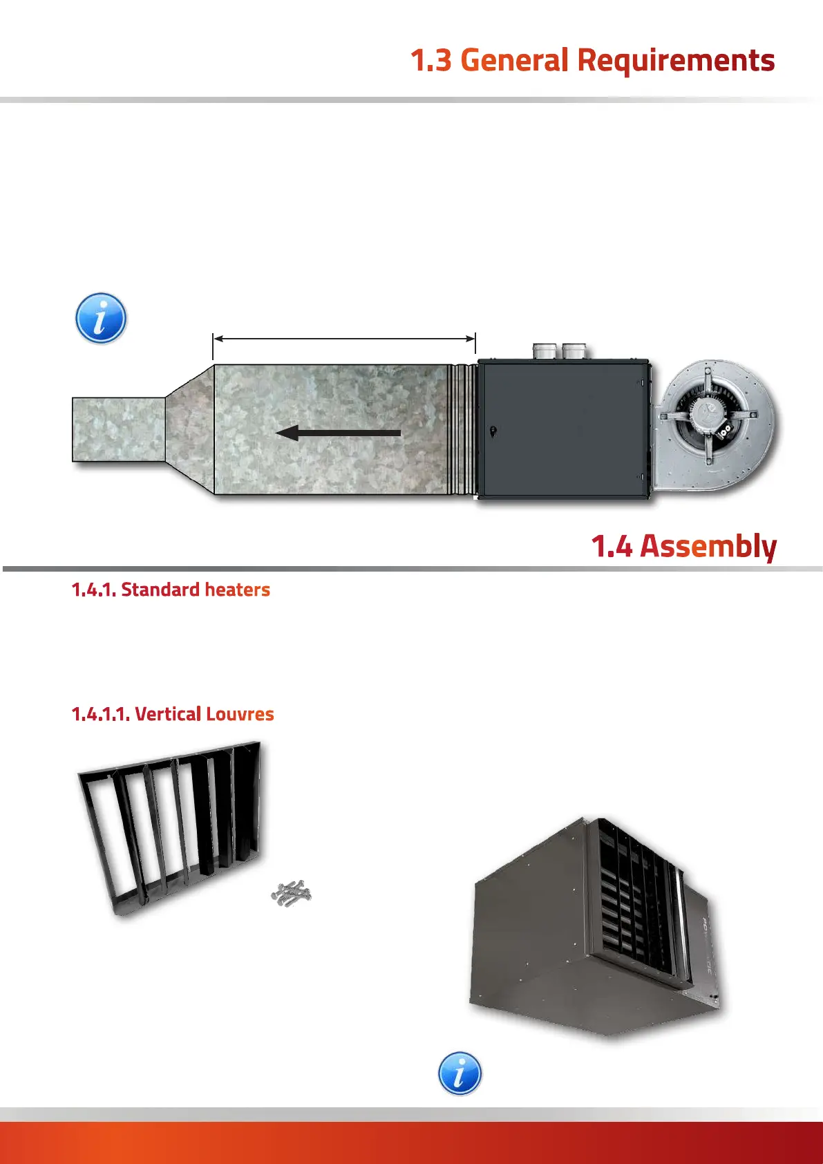
IMPORTANT. It is essential that a minimum 2000mm of straight ductwork, with the same
cross sectional area as the heater outlet be connected to the heater prior to any restriction
LX CCF Heater Unit
Airflow
1.3 General Requirements
Where the heater is installed in a plant room, the return
air intake(s) and the warm air outlet(s) from the heater(s)
must be fully ducted, into and out of the plant room to
avoid interference with the operation of the heater from
other equipment. A full and unobstructed return air path
to the air heater(s) must be provided. The openings in the
structure of the plant room through which the ducting
passes must be fire stopped. Care must be taken to ensure
that return-air intakes are kept clear of sources of smells
and fumes, and where there is any possibility of pollution
of the air by dust, shavings etc., precautions must be
taken to prevent contamination. If necessary suitable
barrier rails should be provided to prevent any combustible
material being placed within 900mm of the outlets.
¹ inlet ducting and outlet ducting. ² Standard EU1/G1 pleated panel
filters to EN779:2002 have a initial pressure drop of circa 50Pa and
final pressure drop of 250Pa. ³ in respect to reducer, bend or
bi-directional section.
1.4 Assembly
1.4.1. Standard heaters
There is no heater assembly required for standard 'F'
(axial fan); 'V' (vertical discharge) or 'C' (close couple fan -
centrifugal blower) as these are supplied complete from
the factory. Assembly of options include:
1.4.1.1. Vertical Louvres
These are supplied as an option and are fitted to the front
of the horizontal louvre utilising the original fixings.
The side and bottom screws of the horizontal front panel
will need to be removed completely. The top screws will
require loosening only.
The Vertical Louvre assembly will have holes to pair with
the screw positioning of the horizontal front panel.
Offer the vertical louvre assembly - flange first, to the
horizontal front panel. The loosened screws will pair with
the slots along the top of the frame. Anchor the frame
onto the screws.
Replace the other screws removed earlier through the
vertical louvre frame and horizontal front panel and into
the body of the heater.
Use the fixings supplied with the kit for any remaining
holes.
Finally adjust the louvres to give the desired airflow.
NOTE: refer to supplement TB145 for detailed
fitting instructions

 Loading...


