page no. 24 of 68
LX Range Users, Installation & Servicing Instructions Doc Ref M110 issue 1.0 Dec 2020.
1.4 Assembly
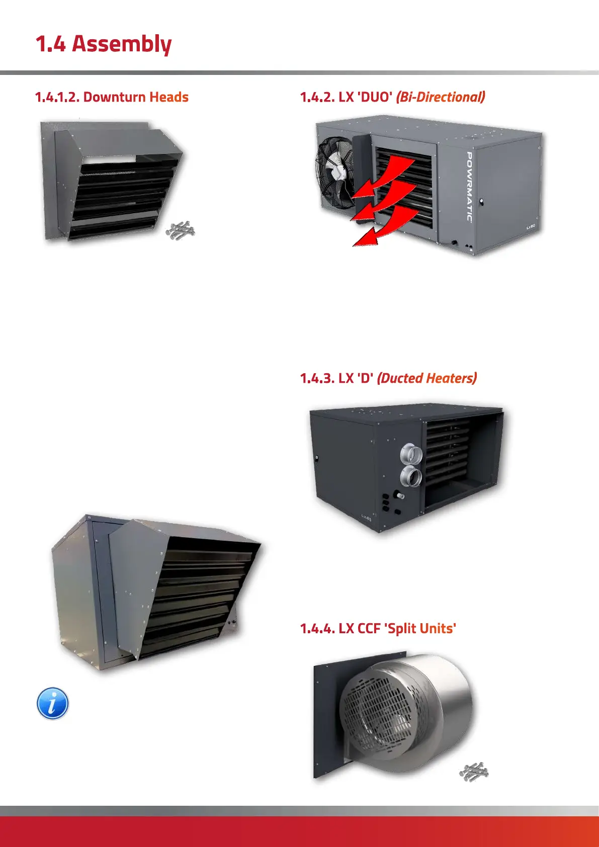
1.4.1.2. Downturn Heads
These are supplied as an option and are fitted in place of
the horizontal louvre utilising the original fixings.
All the screws around the front panel will need to be
removed completely and the pre-fixed front louvre panel
will need to be discarded.
The 30° Downturn Head assembly will have holes to pair
with the screw positioning of the now discarded front
panel.
Insert the 30° Downturn Head assembly - flange first, into
the opening of the heater outlet and hold in position with
a screw.
Replace the remaining screws removed earlier through
the holes of the 30° Downturn Head into the body of the
heater.
Finally adjust the louvres to give the desired airflow.
NOTE: refer to supplement TB146 for detailed
fitting instructions
1.4.2. LX 'DUO' (Bi-Directional)
The heater is suppled with two loose air deflector baffles
to be assembled on-site. One to be fixed to the front of the
heater and one to be fixed to the rear. The three holes
down the flange of the deflector will align with the three
holes pre-punched in the front plate of the heater. Ensure
that the deflector is so positioned that angles towards the
fan on each side.
1.4.3. LX 'D' (Ducted Heaters)
The duct heater is supplied with any air movement fan
but with an inlet and outlet flange (see section 1.2 for
dimensions). This can be used as a heater 'battery' for use
in ductwork or supplied along with a separate Fan Plenum
Box housing a centrifugal fan.
1.4.4. LX CCF 'Split Units'

 Loading...


