8 / 16
Please refer the function code description F7.32, F7.33
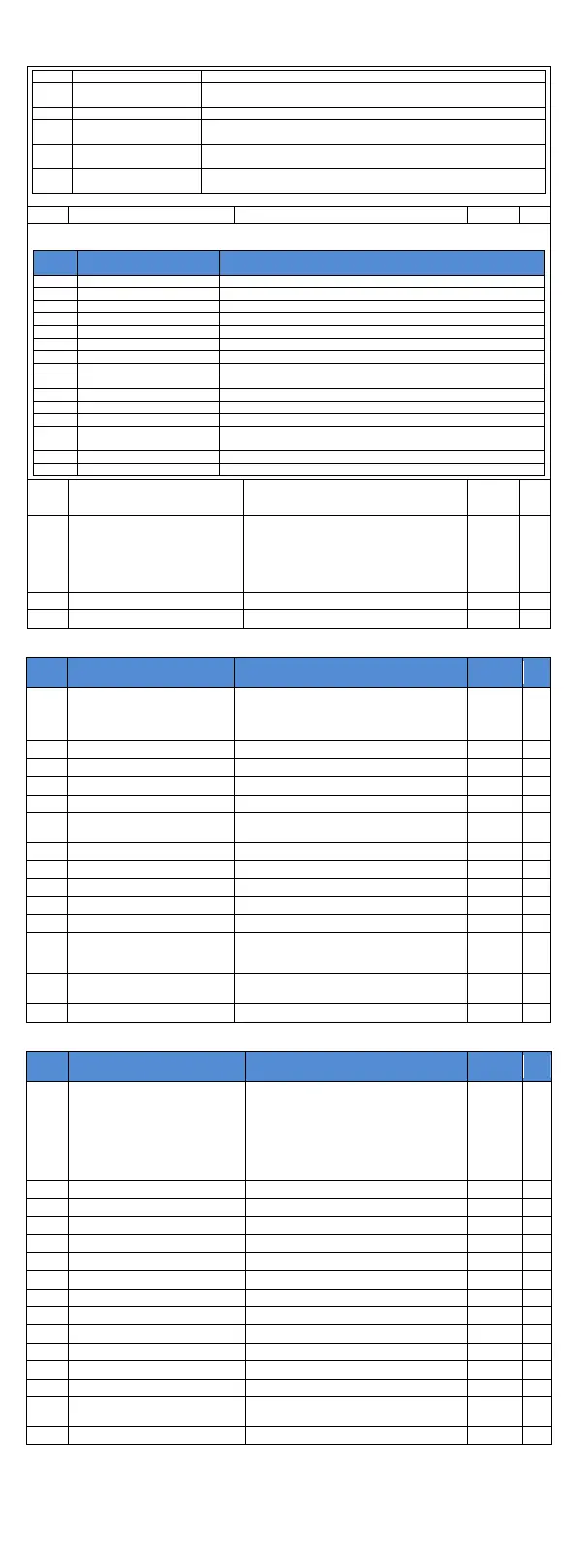
Module temperature
arrival
When the module radiator temperature (F6.06) of the inverter
reaches the set module temperature (F7.40), the ON signal is output.
Please refer the function code description F7.34, F7.35
Lower Limit Frequency
Arrival (Outage)
When the operating frequency reaches the lower limit frequency, the
ON signal is output. The signal is ON in the downtime state.
When the frequency inverter fails and the fault processing mode is to
continue running, the frequency inverter alarm output.
When the starting time of the frequency inverter exceeds the time set
by F7.45, the ON signal is output.
DA1 Output Function Selection
The analog output DA ranges from 0V to 10V, or from 0mA to 20mA. The calibration relationship with the
corresponding functions is shown in the following table:
0 to Maximum output frequency
0 to Maximum output frequency
0 to 2times of rated motor current
0 to 2times of rated motor torque
0 to 1.2times rated frequency voltage
0 to Speed corresponding to maximum output frequency
0.0-100.0 A (Frequency inverter power < 55 kW); 0.0-1000.0 A
(Frequency inverter power > 55 kW)
Relay 1 output delay time
DO output terminal active status
selection
Units digit: SPB switching quantity
0: Positive logic 1: Anti-logic
Tens digit: Relay 1
Hundreds digit: Hundreds digit: Undefined
Thousands digit: SPA
Ten thousands digit: Relay 2
DA1 zero bias coefficient
F3 group Start/stop control parameters group
0: Direct startup
1: Reserve
2: Pre-excitation start (AC asynchronous
motor)
Hold time for start frequency
DC beforehand field current
DC excitation time beforehand
0: Deceleration parking
1: Free stop
0.00Hz to F0.19 (Maximum frequency)
0: Linear acceleration and deceleration
1:S curve acceleration and deceleration A
2:S curve acceleration and deceleration B
Proportion of S curve
start-section:
0.0% to (100.0%. to F3.15)
Proportion of S curve end-section
0.0% to (100.0%. to F3.14)
F4 group V/F control parameters group
0:Straight line V/F;
1:Multipoint V/F; 2:Square V/F;
3:1.2 square V/F;
4:1.4 Square V/F;
6;1.6 Square V/F;
8:1.8 Square V/F;
10:V/F completely separated;
11:V/F Semi separation
0.0%(Automatic torque boost)0.1 to 30%
Torque boost cut-off frequency
0.00Hz to F0.19(Maximum frequency)
Multipoint V/F frequency point 1
Multipoint V/F voltage point 1
Multipoint V/F frequency point 2
Multipoint V/F voltage point 2
Multipoint V/F frequency point 3
F4.05 to b0.04(Rated frequency of motor)
Multipoint V/F voltage point 3
Slip compensation coefficient
Oscillation suppression gain
V/F separation voltage source
V/F separation voltage digital
setting
0V to rated motor voltage
V/F separation voltage rise time

 Loading...