Power up
0000
PASSW.
Txt 1
ON
OFF
3
3
0000
9999
1 2
NO
ADV.SET
Txt 2
NO
YES
1 2
3
YES
CA.SH
Txt 3
NO
YES
1 2
3
YES
CA.BR
Txt 4
NO
YES
1 2
3
YES
ADV.SET
Txt 2
3
DIR
CH2.FUN
Txt 7
DIR
INV
1 2
3
DIR
CH1.FUN
Txt 7
DIR
INV
1 2
3
1.1
CA.SH
OFF
Txt 18
ON
CA.BR
Txt 19
1.0
9202 - Product Version 9202-003 19
1.0=Defaultstate
Line 1 shows status for channel 1 and
channel 2.
Line 2 shows status for sensor 1.
Line 3 shows status for sensor 2.
Line 4 indicates whether the module
is SIL-locked.
1.1=Onlyifpassword-protected
1.2=Ifpasswordhasbeenset.
Line 1 symbols:
=OK.Flashing=error
Line 2 and 3 symbols:
Inputfrequency>1Hz=
Line 4 symbols:
Staticdot=SIL-locked
Flashingdot=notSIL-locked
Continued on the page
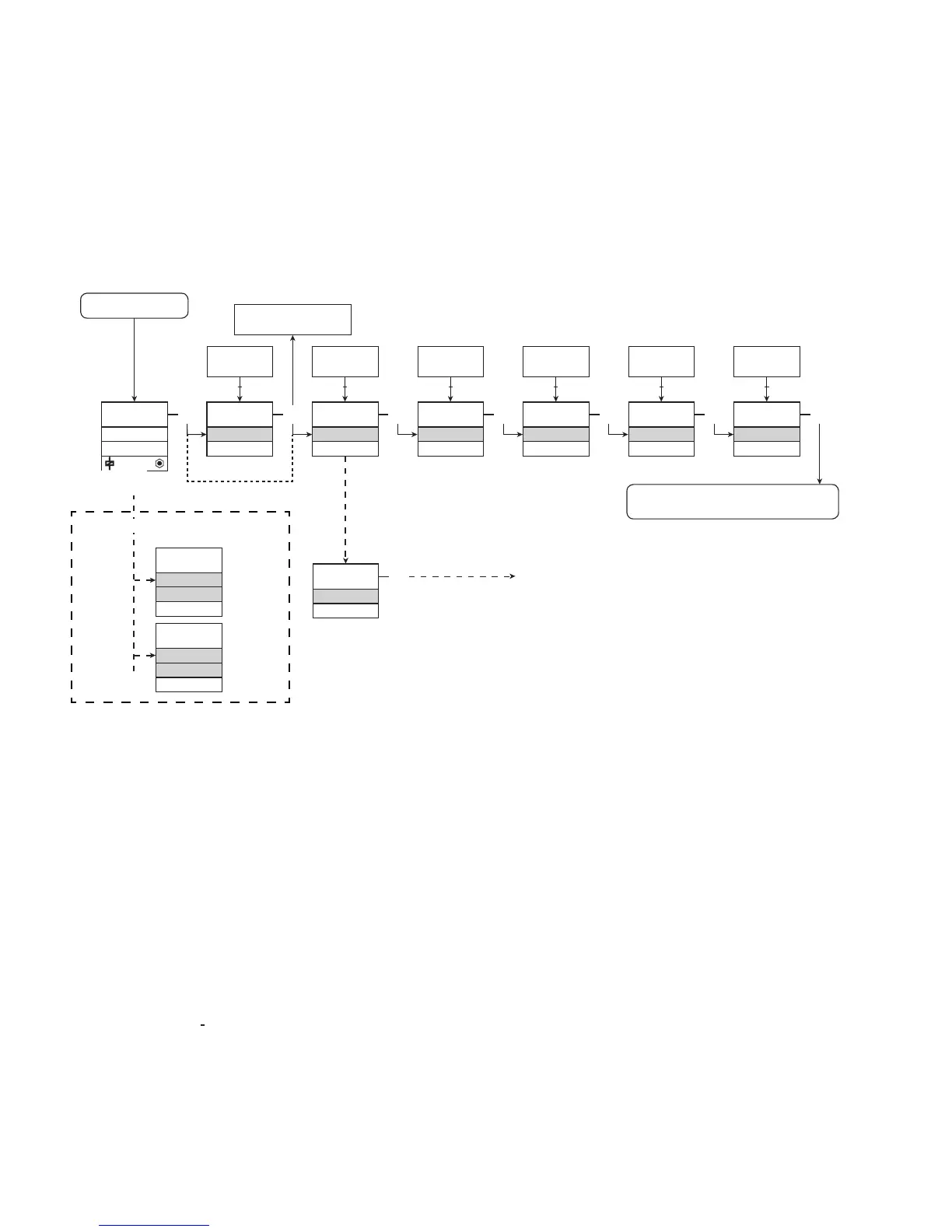
Routing diagram ADV.SET
ROUTING DIAGRAM
If no key is activated for 1 minute, the display will return to the default
state 1.0 without saving configuration changes.
1 Increase value / choose next parameter
2 Decrease value / choose previous parameter
3 Save the chosen value and proceed to the next menu
Hold 3 Back to previous menu / return to menu 1.0 without saving
To default state 1.0
If SIL-locked
directly to [EN.SIL]
Red text signifies safety
parameters in a SIL configuration.
See safety manual for details
Error indication, examples