4.4 Safe parameterisation
The user is responsible for verifying the correctness of the configuration
parameters. (See section 14 Safe parameterisation - user responsibility).
Manual override may not be used for safety applications.
4.5 Installation in hazardous areas
The IECex Installation drawing, ATEX Installation drawing and FM
Installation drawing shall be followed if the products are installed in
hazardous areas.
5. Functional specification of the safety functions
Pulse isolator as well as supply of NAMUR sensors and mechanical switches with
cable error detection installed in the hazardous area. Cable error detection only
works with NAMUR sensors or with the use of external resistors R
s
and R
p
. See
connections diagram at page 13 (switch, cable fault) .
6. Functional specification of the non-safety functions
The status relay (terminal 33 and 34), error signal on power rail (terminal 91) and
LED outputs are not suitable for use in any Safety Instrumented Function.
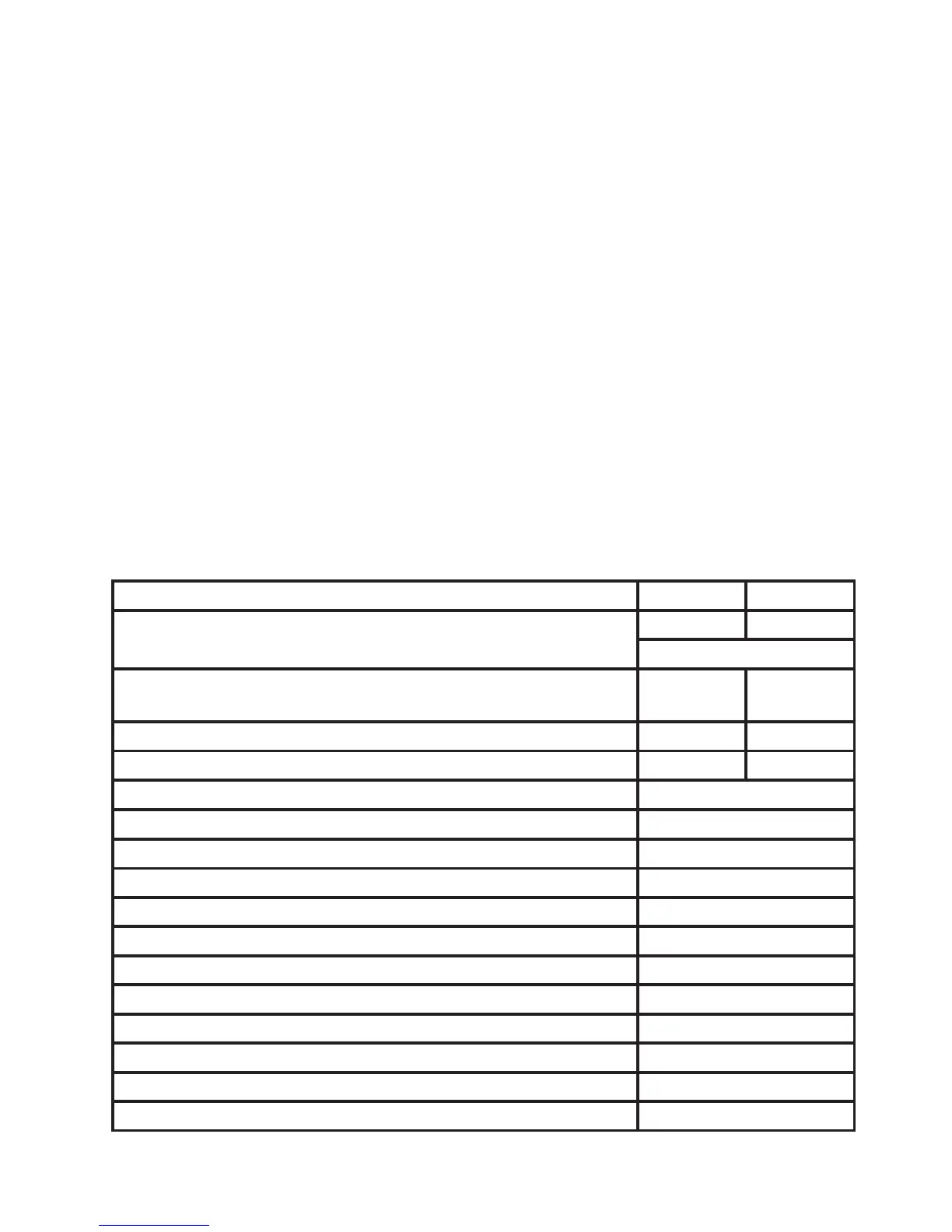
7. Safety parameters
Relay Opto
Probability of dangerous Failure per Hour (PFH) 4.66E-8 3.62E-8
Note
1
, Note
2
Probability of failure on demand (PFD) -
1 year proof test interval
2.04E-4 1.58E-4
Proof test interval (10% of loop PFD) 4 years
5 years
Safe Failure Fraction 90% 91%
Demand response time, opto output
<125
µs
Demand response time, relay output
<10 m
s
Demand mode High
Demand rate 1000 s
Mean Time To Repair (MTTR) 8 hours
Diagnostic test interval 10 seconds
Hardware Fault Tolerance (HFT) 0
Component Type B
SIL capability SIL 2
Description of the “Safe State”, opto output High impedance
Description of the “Safe State”, relay output De-energised
Relay lifetime (Note
2
) 100 000 times