10
Copyright © 2020 Quality Machine Tools, LLCPM-1440GT v9 2020-10
CHUCKS & FACEPLATE
The spindle nose on the PM-1440GT accepts D1-5 Camlock
chucks, faceplates and other work holding devices.
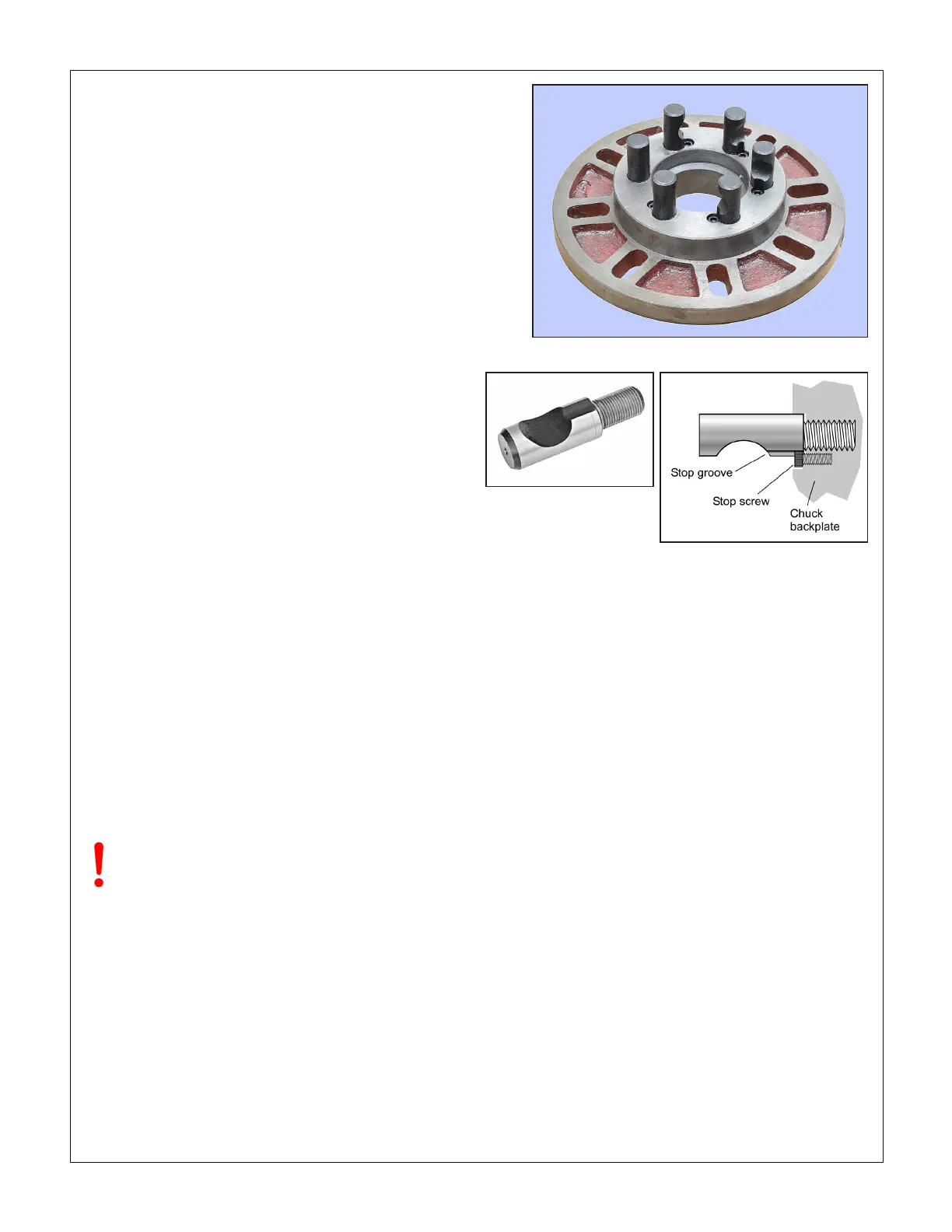
A D1-5 chuck or faceplate is held by six threaded studs, each
with a D-shape crosscut to engage a corresponding cam in
the spindle nose, Figures 3-4, 3-5. The function of the cams is
to pull the chuck backplate inward to locate its internal taper
rmly on the spindle nose.
Alongside each stud is a stop screw, the head of which ts
closely in a groove at the threaded end of the stud. The func-
tion of the stop screw is not to clamp the stud in place, but
instead to prevent it from being unscrewed when the chuck is
out on the bench.
Figure 3-5 Camlock stud
TO INSTALL A CHUCK
Disconnect the 220V supply from the lathe!
D1-5 chucks and faceplates are heavy, some more than 30
lb. They will cause serious damage if allowed to fall. Even if a
chuck is light enough to be supported by one hand, the lathe
bed should be protected by a wood scrap, as Figure 3-6. Some
users add packing pieces, even custom-made cradles, to as-
sist “straight line” installation and removal.
Before installing make certain that the mating surfaces of the
chuck/faceplate and spindle are free of grit and chips.
The cams on the spindle are turned with a square-tip wrench
similar to the chuck key (may be same tool in some cases).
Recommended procedure:
1. Disconnect power from the machine. Then, select the high-
est spindle speed (2000 rpm) to allow easier hand rotation
of the spindle. (Alternatively, try moving the speed selec-
tion levers between detents to nd a “between teeth” con-
SADDLE FEED DIRECTION
The control knob with pointer below the speed selectors, Figure
3-1, determines whether the saddle feed is right to left — the
usual direction for turning and thread cutting — or reversed.
The selected direction applies to both the leadscrew and the
saddle/cross-slide power feed. Power feed is OFF when the
knob is at 12 o'clock position, as in the photo.
Before changing feed direction, STOP THE MOTOR. Hand-
turn (jiggle) the spindle while feeling for the mesh, as above.
To disengage the power feed, set the Saddle Feed lever to its
mid-position.
More information on the power feed system is provided later in
this Section, see Saddle Feed Gearbox.
Figure 3-4 D1-5 faceplate
All stop screws must be present & fully tightened!
Camlock action can jam any stud lacking a stop
screw — a serious problem.
JOG FEATURE
"Jog" is momentary-type push-button, active only if the Motor
Control lever is in the mid-travel (OFF) position, Figure 3-2.
Press the button briey to "nudge" the spindle forward by a
few degrees. Jog can be used to reposition the chuck and/or
workpiece, especially useful when low spindle-speed gearing
makes hand rotation dicult.
The control system can be rewired for "Reverse Jog", see the
electrical diagram, Section 5.

 Loading...

